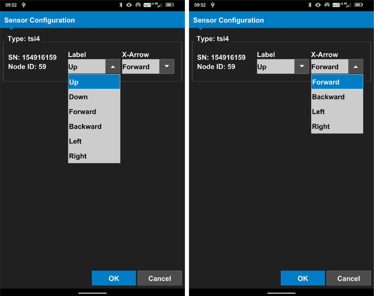
These orientations are available for the TS-i4 body sensor.
Note: The hardware kit for the 2D Indicate CTL system is a base kit. This base kit is used with other components on all the other CTL systems.
Select a location to install the TS-i4 body sensor that is:
ADDITIONAL INFORMATION:
Below the cab in an area with minimum possible damage. The belly pan of the machine is the recommended location.
In an area with sufficient clearance for the sensor connections, strain relief plates, and the cover.
Where the TS-i4 IMU target measurement is easily interchanged to the machine body with a known offset.
Note: Do not install the TS-i4 sensor externally on the machine.
Prepare the installation area. Remove dirt, mud, or material from the installation location of the sensor weld plate.
Mark around the weld plate location with a permanent marker.
Grind the outlined area to remove the paint to prepare for weld.
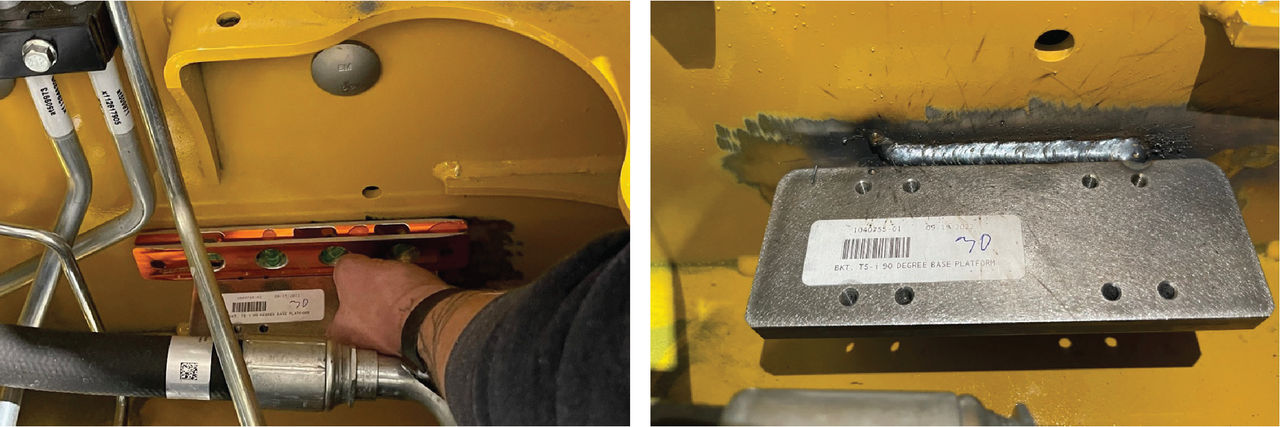
Set the plate and and make it level. Make sure that the plate is in less than 2 degrees of the nearest horizontal edge.
ADDITIONAL INFORMATION: Figure: Position and level plate
Warning: Weld heat can release poisonous smoke. Obey the standards to remove paint in the weld area. Wear an applicable respirator or mask.
Weld the 90-degree bracket to the machine.
Remove the weld slag with a slag hammer or other correct tool.
Clean the weld with a wire brush to prepare it for paint.
Paint the plate and welds with a rust-preventive paint to prevent rust and corrosion.
ADDITIONAL INFORMATION:
Note: It is usually easier to connect the M12 CAN connectors before you attach the TS-i4 sensor to the plate/bracket.
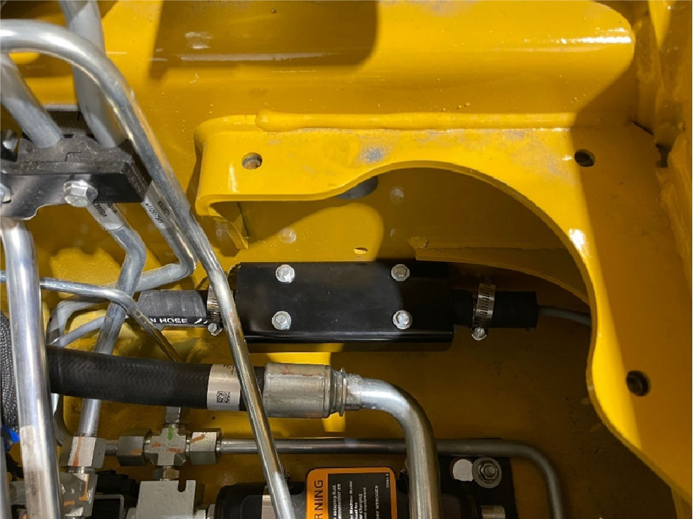
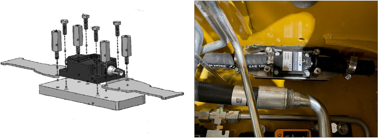
Carefully install the TS-i4 sensor on the cool weld plate.
Use a strain relief plate for each cable connection.
Supply protection for the M12 cables with hydraulic hose.
ADDITIONAL INFORMATION: Figure: Generic TS-i4 body sensor assembly
The pictures show some samples of TS-i4 mount locations.
Figure: Bobcat body sensor mounting locationsFigure: Takeuchi body sensor mounting locationFigure: Caterpillar body sensor mounting location
Notice: For 2D Indicate Body systems, install a terminator on the TS-i4. For all other systems, put the 7 m M12 Turck cable through the access slot to the outside of the boom arm. Refer to the related topic 2D Hitch add-on installation.
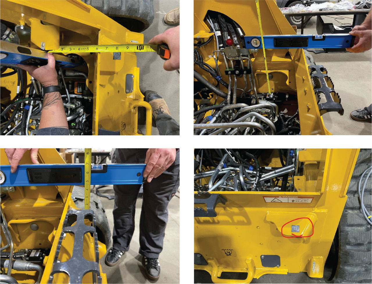
Transpose the TS-i4 crosshair to an area outside the body where you can take a measurement.
ADDITIONAL INFORMATION: Figure: TS-i4 crosshair transposed to outside machine
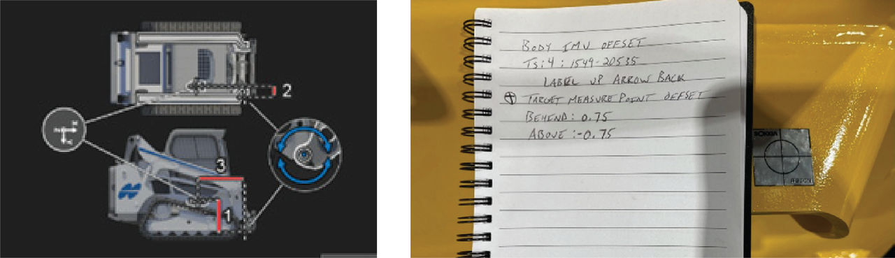
With the crosshair and associated offsets, measure IMU Above (1), IMU Inside (2), and IMU Behind (3).
Record the IMU serial number and orientation. This information is necessary to continue.
ADDITIONAL INFORMATION:
Install the cover of the TS-i4 sensor.
ADDITIONAL INFORMATION: Figure: TS-i4 body sensor cover installed
Run the 3 m M12 cable from the TS-i4 back to the location for the MC-X1. Make sure that the TS-i4 M12 cable goes to the M12 Tee on the MC-X1 Breakout Cable A.
ADDITIONAL INFORMATION:
Note: For Dual GNSS Mastless systems, replace the terminator with an M12 cable to the cab roof.
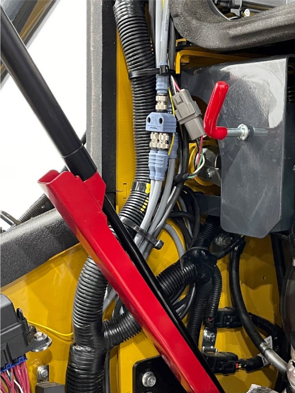
Run a 5 m M12 cable from the TS-i4 Body sensor from the belly pan to the boom arm.
Run the 7 m M12 cable for J1939 down into the machine belly pan and follow the 5 m M12 cable. The two cables go into the machine bulkhead adjacent to the hydraulic coupler.
ADDITIONAL INFORMATION:
Note: For systems with J1939 for attachment CAN and Topcon 2D sensors, it is necessary to connect the 7 m M12 cable to the M12 Tee on the MC-X1 Breakout B cable.
Mark one of the cables clearly on the end to easily identify CANopen and J1939.
ADDITIONAL INFORMATION: Figure: M12 cable routed from TS-i4 body sensor

 Warning: Weld heat can release poisonous smoke. Obey the standards to remove paint in the weld area. Wear an applicable respirator or mask.
 The pictures show some samples of TS-i4 mount locations.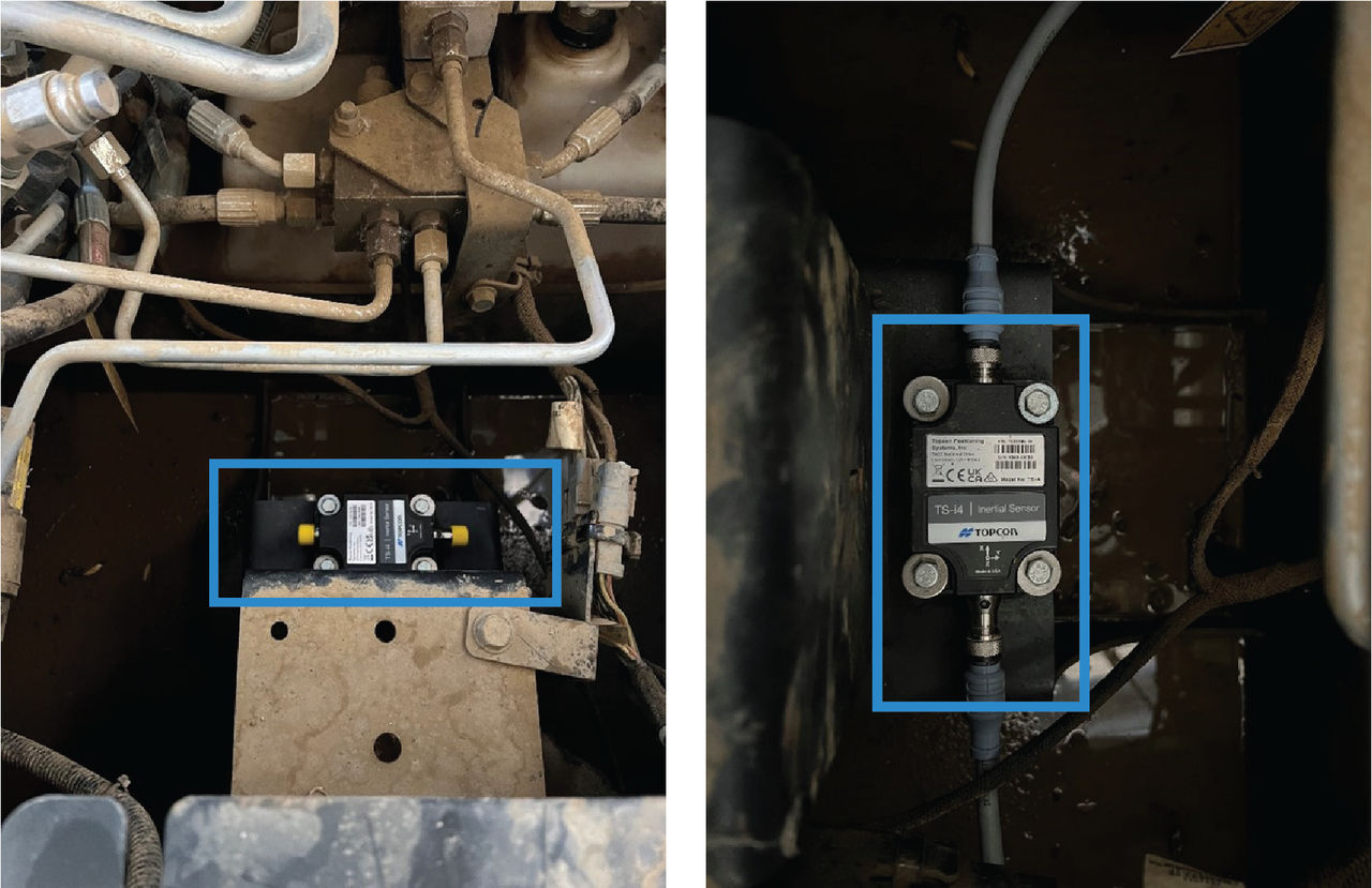
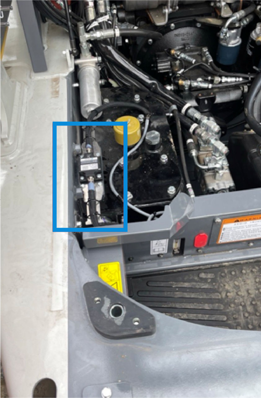
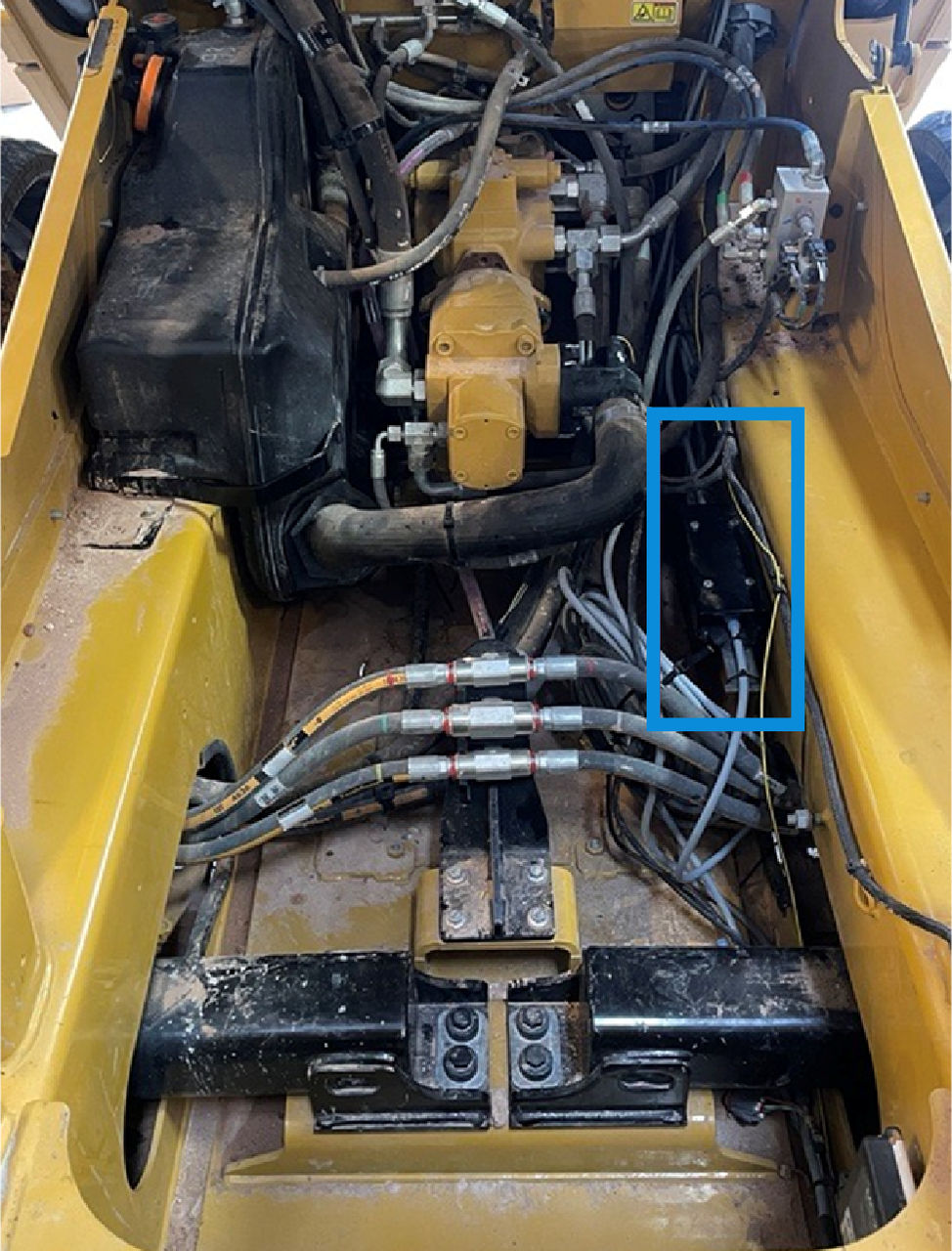 Notice: For 2D Indicate Body systems, install a terminator on the TS-i4. For all other systems, put the 7 m M12 Turck cable through the access slot to the outside of the boom arm. Refer to the related topic 2D Hitch add-on installation.