- Select Box Blade from the Type list.
- Select the attachment Make/Model.ADDITIONAL INFORMATION:
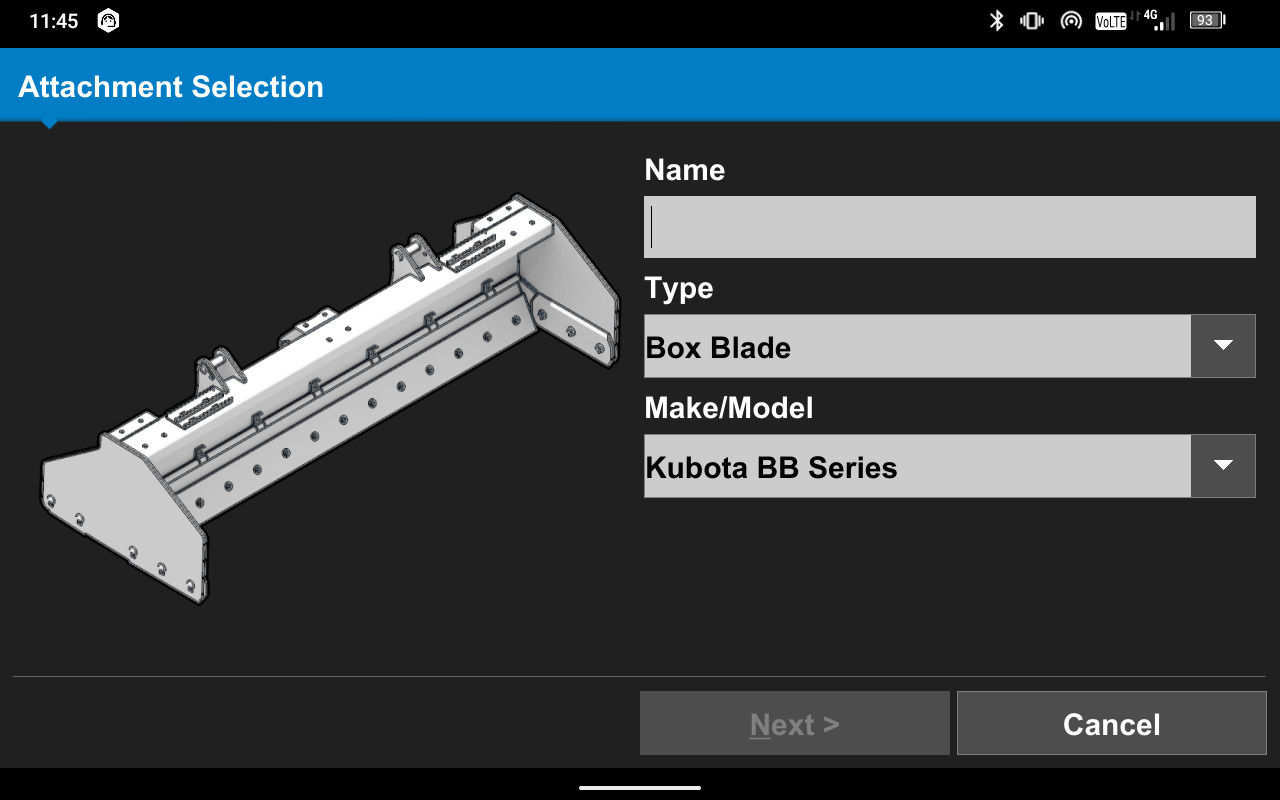
- Add Next.ADDITIONAL INFORMATION:Note: The Make/Model selection determines the CAN communication from the SC024 controller to the MC-X1 controller. The system does not engage Automatic Control if the selection is not correct.
- Complete the onscreen illustrations to measure the right side(1) and left side (2) Blade Wear Bolt Distance.ADDITIONAL INFORMATION:
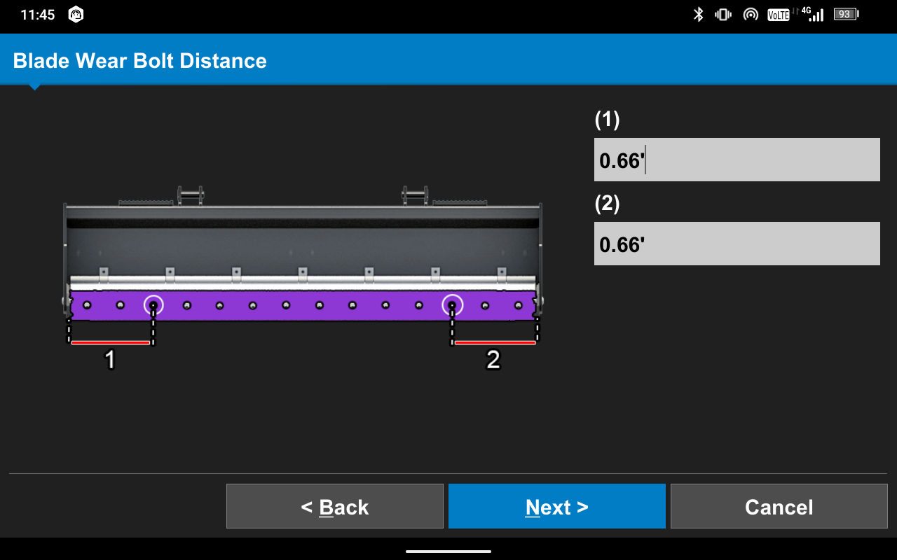
- Select Next.
- Measure from the bottom of the cutting edge to the top of the moldboard for blade Height (1).
- Measure from the bottom right blade corner to the bottom left blade corner for blade Width (2).ADDITIONAL INFORMATION:
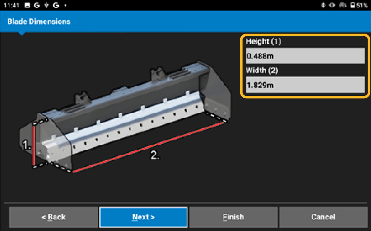
- Select Next.
- Measure the distance between the center of the cutting edge bolt and the bottom of the cutting edge. Enter the measurement for Slant (1).
- Measure the Vertical. Measure straight up from the track plane to the center of the bolt. Enter the measurement for Vertical (2). ADDITIONAL INFORMATION:
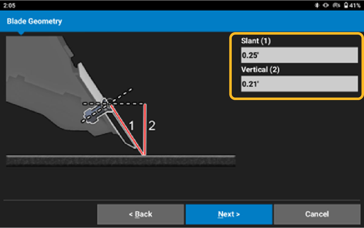
- Select Next.
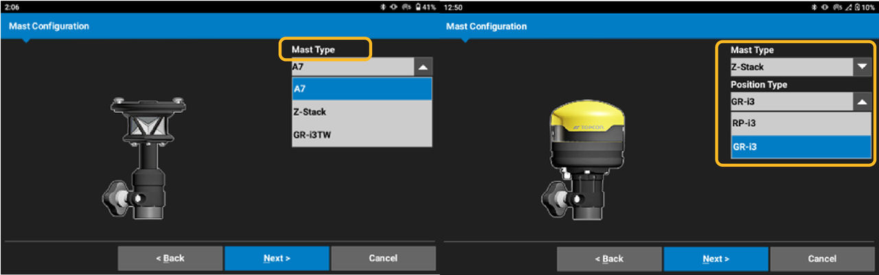
- Select Mast Type. Select Z-Stack for one GR-i3, and then select GR-i3. For RP-i3, select Z-Stack, and then select RP-i3.ADDITIONAL INFORMATION:Note: CAT Mastless Grader blade and Box blade does not show Mast Configuration and Mast Dimensions.
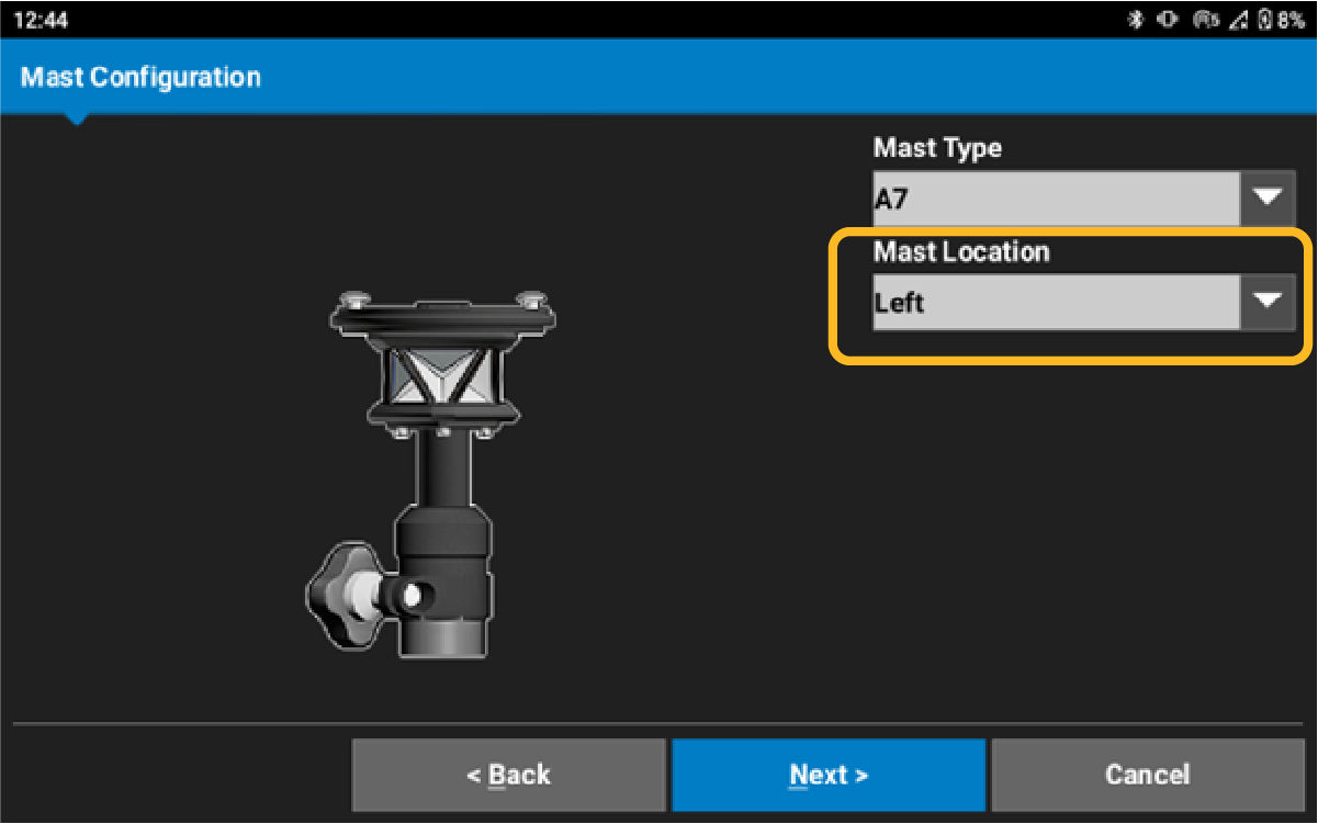
- Select the or Right side from the operator’s seat.ADDITIONAL INFORMATION:
- Select Next.ADDITIONAL INFORMATION:
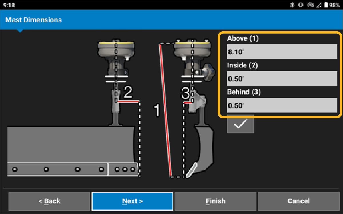
- Measure from the snap point of the GR-i3 or the center of the A7 prism to the bottom of the cutting edge for (mast) Above (1) measurement.
- Measure from the bottom, left or right based on mast placement, outside of the cutting edge to the center of the GR-i3 or prism for (mast) Inside (2) measurement.
- Measure from the bottom of the cutting edge to the center of the GR-i3 or prism for (mast) Behind (3) measurement.
- Select Next.
- Assign the TS-i4 Hitch sensor. Select the Sensor ID drop-down menu. Use the recorded information from the installation. Select the Sensor ID.
- Select the Wrench icon and then select the TS-i4 Hitch sensor IMU orientation. ADDITIONAL INFORMATION:
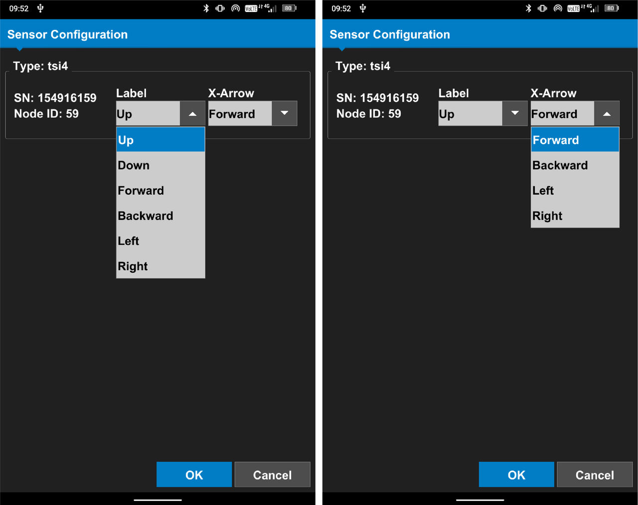
- Select OK.ADDITIONAL INFORMATION:

- Measure from the center of the right side hitch pivot pin to the center of the IMU crosshair for IMU Above (1) measurement.
- Measure from the center of the right side hitch plate pivot pin to the center of the IMU crosshair for IMU Inside (2) measurement.
- Measure from the center of the right side hitch plate pivot pin to the center of the IMU crosshair for IMU Behind (3) measurement.
- Select Next.ADDITIONAL INFORMATION:Note: It is necessary for CAT Mastless Grader blade and Box blade configurations to have another measurement. To set up a Masted configuration, go to the Blade Pivot Point measurements.
- Assign the TS-i4 C-Frame sensor. Select the Sensor ID drop-down menu. Use the recorded information from the installation. Select the Sensor ID.
- Select the Wrench icon and select the TS-i4 Blade sensor IMU orientation. ADDITIONAL INFORMATION:
- Select OK.ADDITIONAL INFORMATION:
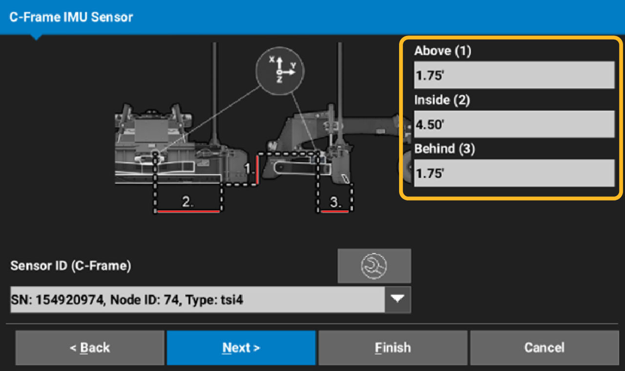
- Measure Above (1), from the track plane to the center of the C-Frame IMU crosshair.
- Measure Inside (2), from the right side blade corner to the center of the C-Frame IMU.
- Measure Behind (3), from the cutting edge to the center of the C-Frame IMU crosshair.
- Select Next.
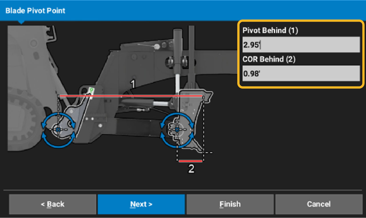
- Measure Pivot Behind (1), from the cutting edge to the right side hitch plate pivot pin.
- Measure COR Behind (2), from the cutting edge to the blade center of rotation pivot point.ADDITIONAL INFORMATION:
- Select Next.
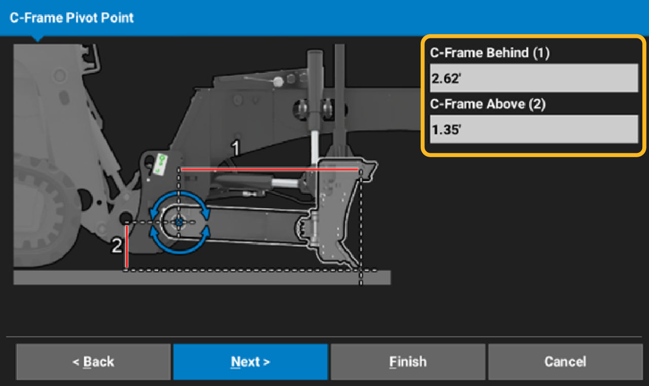
- Measure C-Frame Behind (1), from the cutting edge to the C-Frame pivot pin.
- Measure C-Frame Above (2), from the cutting edge to the C-Frame pivot pin.ADDITIONAL INFORMATION:
- Select Next.
- Assign the TS-i4 Blade sensor. Select the Sensor ID drop-down menu. Use the recorded information from the installation. Select the Sensor ID.
- Select the Wrench icon and select the TS-i4 Blade sensor IMU orientation.ADDITIONAL INFORMATION:
- Select OK.ADDITIONAL INFORMATION:
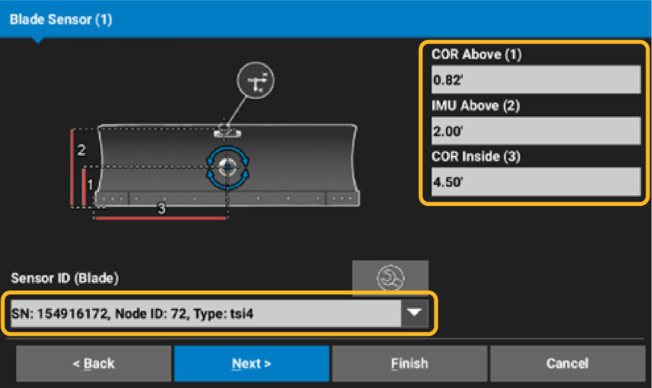
- Measure COR Above (1), from the track plane to the center of the blade rotation point.
- Measure IMU Above (2), from the track plane to the center of the Blade IMU crosshair.
- Measure COR Inside (3), from the right blade corner to the center blade rotation point.
- Select Next.
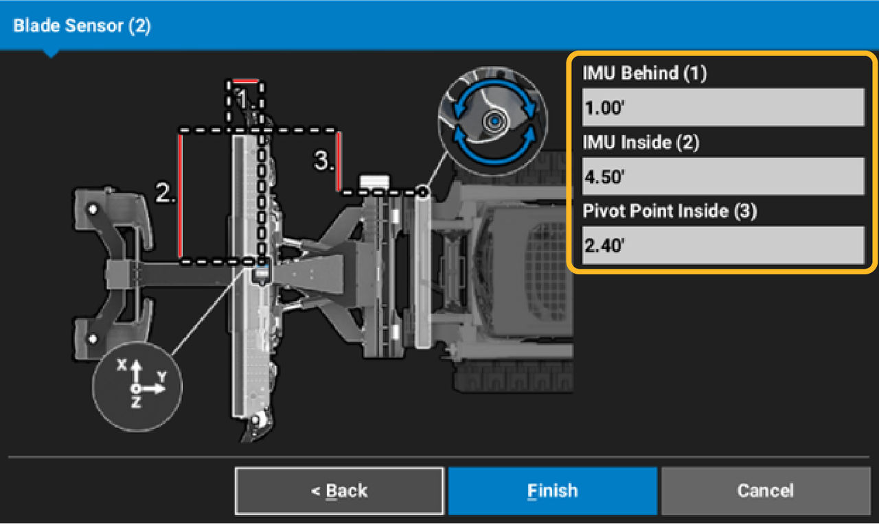
- Measure IMU Behind (1), from the cutting edge to the center of the Blade IMU crosshair.
- Measure IMU Inside (2), from the right side blade corner to the center of the Blade IMU crosshair.
- Measure Pivot Point Inside (3), from the right side blade corner to the center of the right side hitch plate pivot pin.ADDITIONAL INFORMATION:
- Select Finish.
- Select to set as Active Attachment or not.
myTopcon NOW! support
Take your Topcon experience to the next level with myTopcon NOW! This platform is a self-service tool for your desktop or mobile device.