Looking for your apps? Click the account icon in the upper right corner of the page.
TS-i4 IMU sensor orientation
An additional TS-i4 body sensor is necessary for the CAT next gen LPS system configuration. For a proper installation, refer to the system diagram in the GNSS and LPS system termination topic.
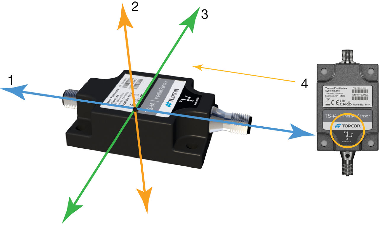
The TS-i4 IMU sensor orientation aligns with the X, Y, and Z axes. Z runs up and down, X runs lengthwise across the sensor and through the connectors, and Y runs across the width or the edge with no connectors.
Figure: TS-i4 IMU sensor orientation
X axis
Z axis
Y axis
X axis direction
Mount the sensor parallel to the axis being measured. This does not make system performance better, but squaring the sensors to each part of the machine makes for a clean installation. All sensor mounting configurations are supported.
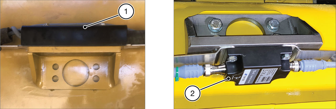
Note: You can install the TS-i4 IMU sensors and platform brackets upright or rotated 180 degrees, so the label of the sensor faces down.
Figure: Sensor bracket orientation assemblies
Sensor up
Sensor down
Notice: A sensor serial number that ends with 00 is a special CAN identifier. 3D-MC automatically changes it to 01. This can cause a conflict if another sensor serial number already ends in 01. The system cannot support sensors with identical CAN identifiers. Carefully review the sensor serial numbers before installation to make sure that there are no redundant CAN identifiers.