This procedure is only applicable for the LPS system configuration with a Prism (LPS) sensor type, which uses the TS-i4 only as a body sensor.
- Power up the system. Allow several minutes for the 3D-MC software to detect the TS-i4 Body Sensor.
- Position the machine on a flat and stable surface, free of obstructions.
- Curl the stick and bucket in, as close as possible. This will reduce tipping errors.ADDITIONAL INFORMATION:
Figure: Stick and bucket curled in 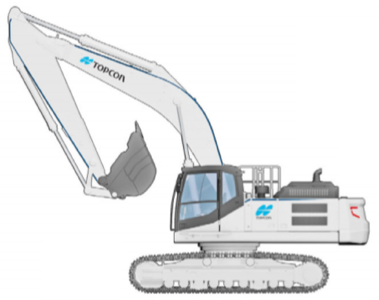
- In 3D-MC, select .
- On the Sensor Calibration screen, select the right Sensor Orientation and select Calibrate.ADDITIONAL INFORMATION:
Figure: Sensor calibration 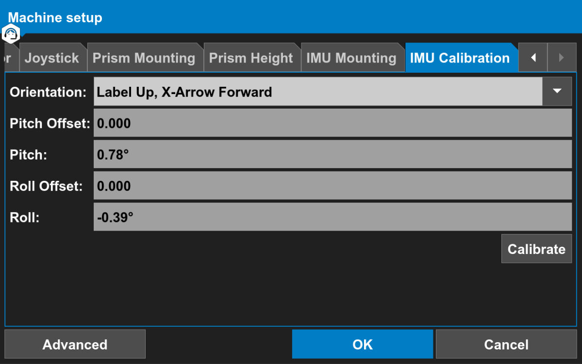 ADDITIONAL INFORMATION:Note: It is not necessary to identify the TS-i4 body sensor with the NODE ID because it is the only sensor connected to the CAN line.The Body Sensor calibration starts. The IMU Calibration screen shows position 1.
Figure: IMU calibration - position 1 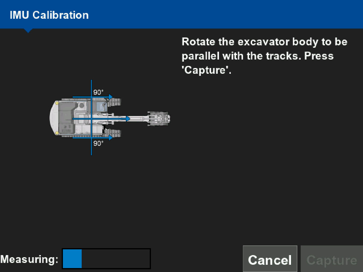
- Rotate the excavator body parallel to the tracks.
- Select Capture.ADDITIONAL INFORMATION: The IMU Calibration screen shows position 2.
Figure: IMU calibration - position 2 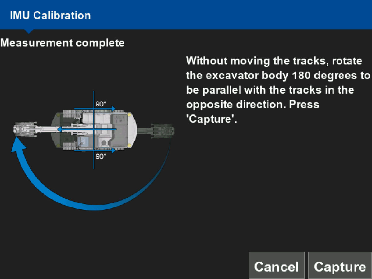
- Without moving the excavator tracks, rotate the body 180 degrees to be parallel to the tracks in the opposite direction.
- Select Capture.ADDITIONAL INFORMATION: The IMU Calibration screen shows position 3.
Figure: IMU calibration - position 3 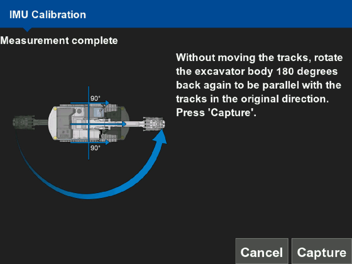
- Without moving the excavator tracks, rotate the body 180 degrees back to be parallel with the tracks in the original direction.
- Select Capture.ADDITIONAL INFORMATION: The IMU Calibration screen shows the calibration as complete with the body IMU calibration data.
Figure: IMU calibration data 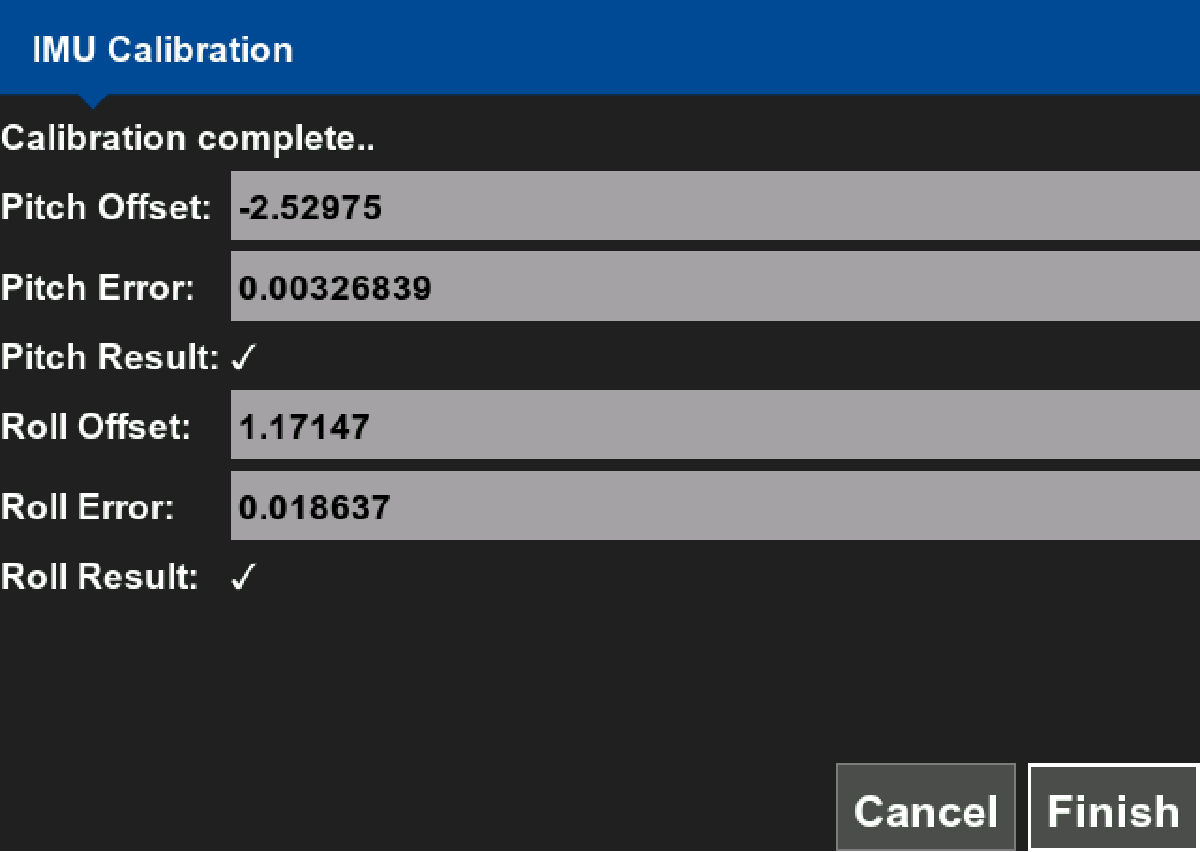
- Select Finish to accept the body IMU calibration results.
Previous:
System calibration
Next:
Bucket calibration
myTopcon NOW! support
Take your Topcon experience to the next level with myTopcon NOW! This platform is a self-service tool for your desktop or mobile device.