Looking for your apps? Click the account icon in the upper right corner of the page.

MC-X3 controller connections

The MC-X3 uses the MC-X3 breakout cable (P/N 1033631-01) to connect all of the system components.
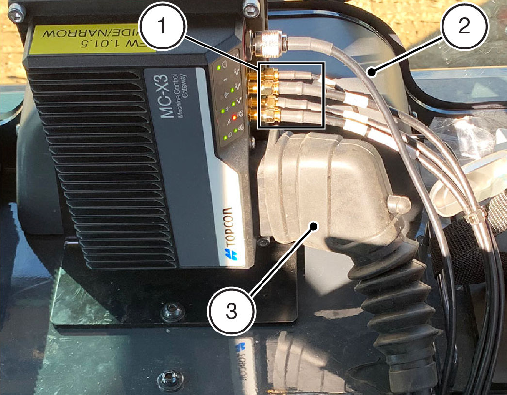
  1. Diversity Antenna Cables
  2. Radio Antenna Cable
  3. MC-X3 Breakout Cable (P/N 1033631-01)
  1. Find each cable (labels on the cable jackets).
  2. Connect the breakout cable to the controller.
  3. Run all cables through the cable seal and into the cab, if not already done.
  4. Connect the four cables from the diversity antenna and the cable from the radio antenna.
  5. Connect the display connector to the GX-Series display, then connect external radio connector to the radio, if equipped.
  6. Connect the cables from the GNSS receivers and TS-i4 sensor circuits to tee.
  7. Connect the tee to the CAN M12 cable on the breakout cable, then connect the J1939 M12 cable on the breakout cable to tee.
  8. Connect a terminator to one of the ports on the tee.
  9. Connect power and ground to the power and ground circuits on machine interface connector.

myTopcon NOW! support

Take your Topcon experience to the next level with myTopcon NOW! This platform is a self-service tool for your desktop or mobile device. 
Product manuals
paper icon
Communications
phone icon
E-learning
hat icon
Quick start guides
support icon
Firmware & software updates
cloud icon
Troubleshooting
webinars icon