- Mount the GR-i3 onto the left or right vibration pole. Connect the M12 cable to the GR-i3 and carefully pull the cable slack.
- The CANOpen bayonet connector on the Topcon bulkhead on the attachment may need to be moved to the left or right side.
- Route the cable and make sure the bayonet connector faces the attachment bulkhead to enable the connection of the CAN coil cord. Make sure that there is no slack in the M12 cable from the GR-i3, and make sure that there is not too much pressure pulling on either end of the M12 connectors.ADDITIONAL INFORMATION:
Figure: GR-i3 GNSS receiver installed on vibration pole 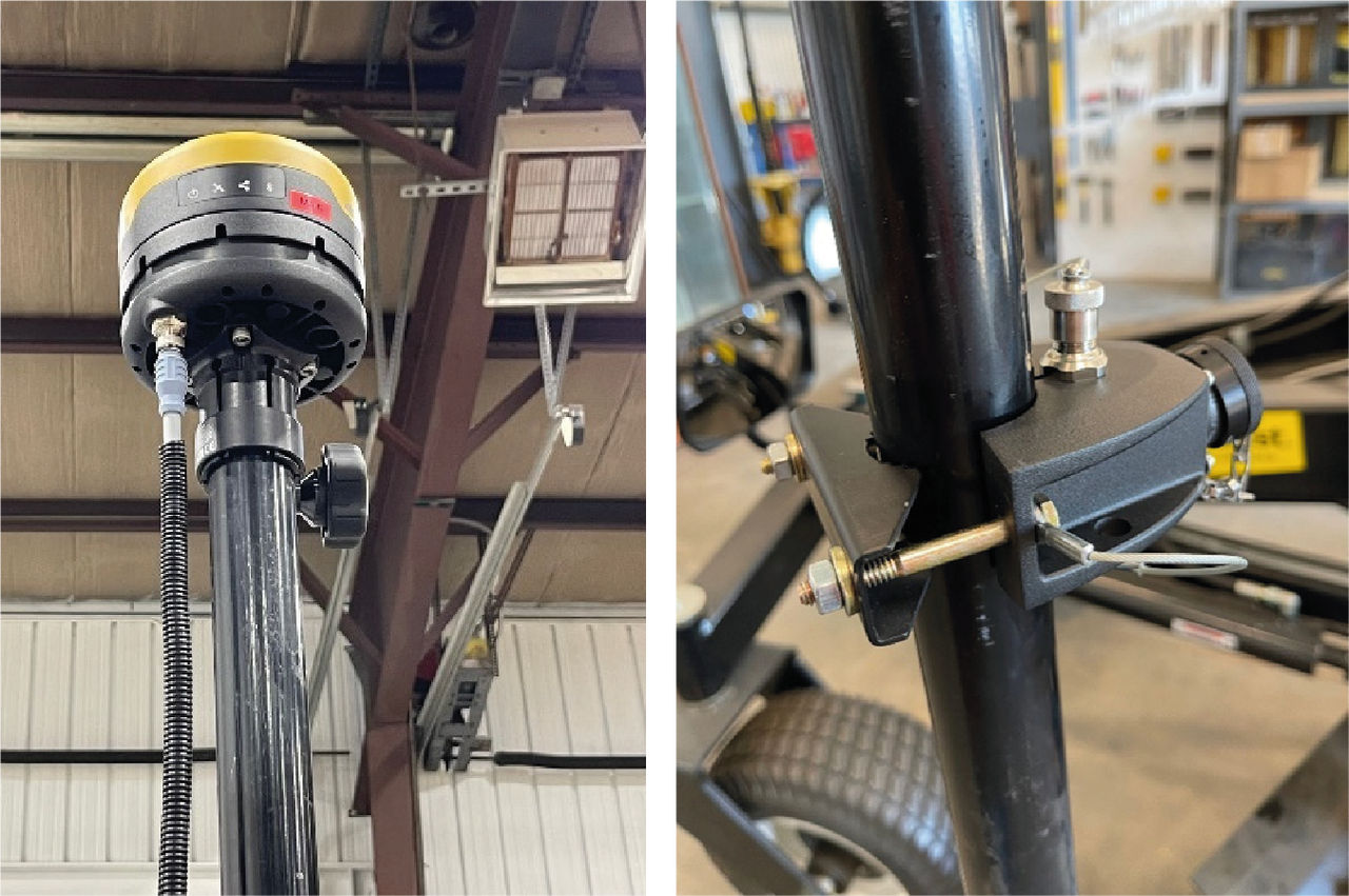
- Bolt down the vibration pole Tee using the adjustable back collar to make sure that no sliding is possible.
- Connect the M12 cable from the GR-i3 to the top M12 connection on the vibration post Tee. Use protection wire loom as necessary. Add zip ties as necessary.
- Install the M12 terminator to the M12 connection on the bottom of the vibration post Tee.
- Connect the elevation coil cord to the vibration post Tee.
- Connect the elevation coil cord to the vibration post Tee. Connect the other end of the elevation coil cord to the attachment bulkhead CANOpen bayonet connector.
- Use the cable strain relief clips on the vibration post Tee and the attachment bulkhead.ADDITIONAL INFORMATION:Notice: Do not plug the coil cord connectors in the J1939 connectors.
Figure: GNSS Control CTL with GB108 attachment 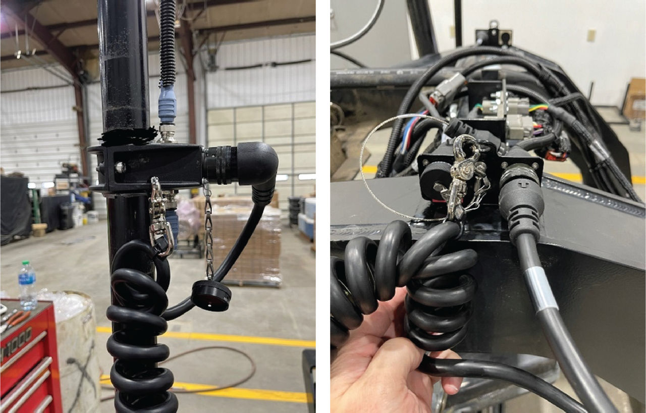
Previous:
LPS control systems mast installation
myTopcon NOW! support
Take your Topcon experience to the next level with myTopcon NOW! This platform is a self-service tool for your desktop or mobile device.