Learn how to configure and calibrate attachments and implements on the Attachments and Implement Setup screens. The options on these screens include coupler selection, wear entry, and calibration steps.
You can change the couplers, add a new attachment or new implement, and edit them on the Attachments screen. The Implement Setup screen shows the correct information for the type of coupler and applicable instruments. On-screen instructions screen move you through the full setup.
- To show the Attachments screen:
- Select the Bucket icon.
- Select .
ADDITIONAL INFORMATION:Figure: Attachments screen path 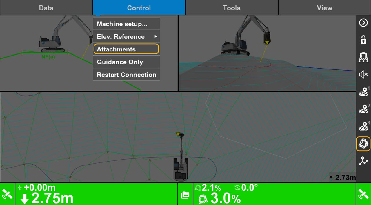 You can select a Coupler from the drop-down list. The field below the drop-down list shows the configured attachments and implements. Use this list to change the coupler or select the necessary attachment. This prevents the incorrect selection of an implement. Also, a tilting or tilting/rotating calibration will not be necessary after a new implement is added.
Figure: Attachments screen 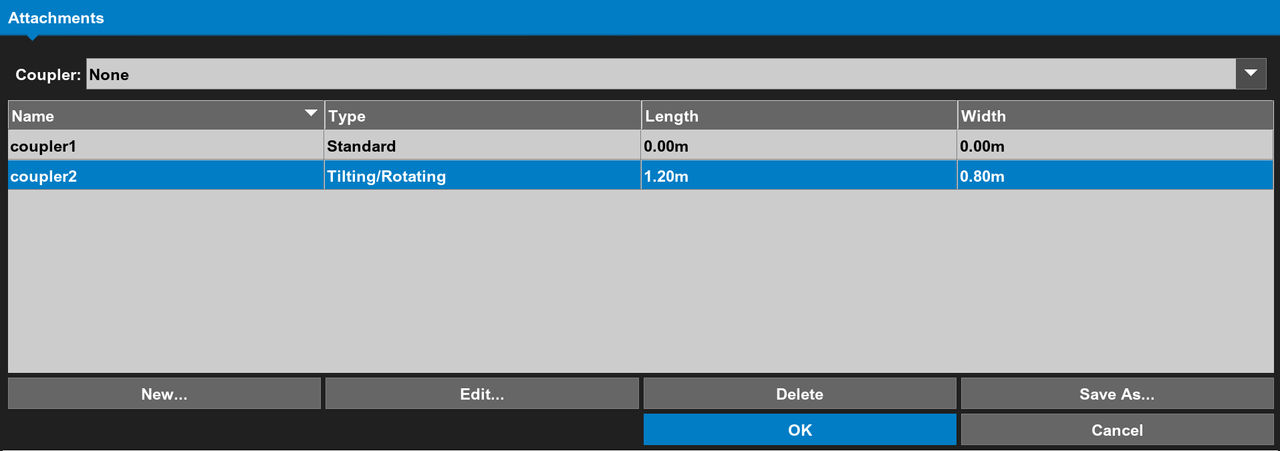
- Select New to show the Implement Setup screen.ADDITIONAL INFORMATION:The controls on the Implement Setup screen are set for the IMU sensor location and the selected coupler configuration. If a TS-i4 is on the hitch, it is necessary to select a Sensor from the drop-down list.
- Select the Toothed or Grading from the Bucket Edge drop-down list.
- Select the implement Type from the drop-down list.ADDITIONAL INFORMATION:The options on the Type drop-down list show the type of coupler.
- Enter the Implement Wear:ADDITIONAL INFORMATION:
Figure: Implement setup 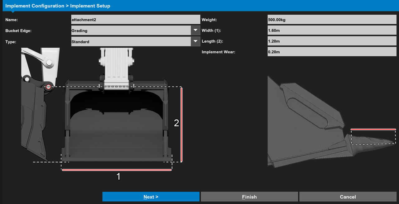
- Measure the Length of the teeth or edge.
- Enter the length of the teeth or edge.
- Select Next.
- Select the Orientation from the drop-down list on the IMU Position screen.
- Select Next.ADDITIONAL INFORMATION:
Figure: IMU position 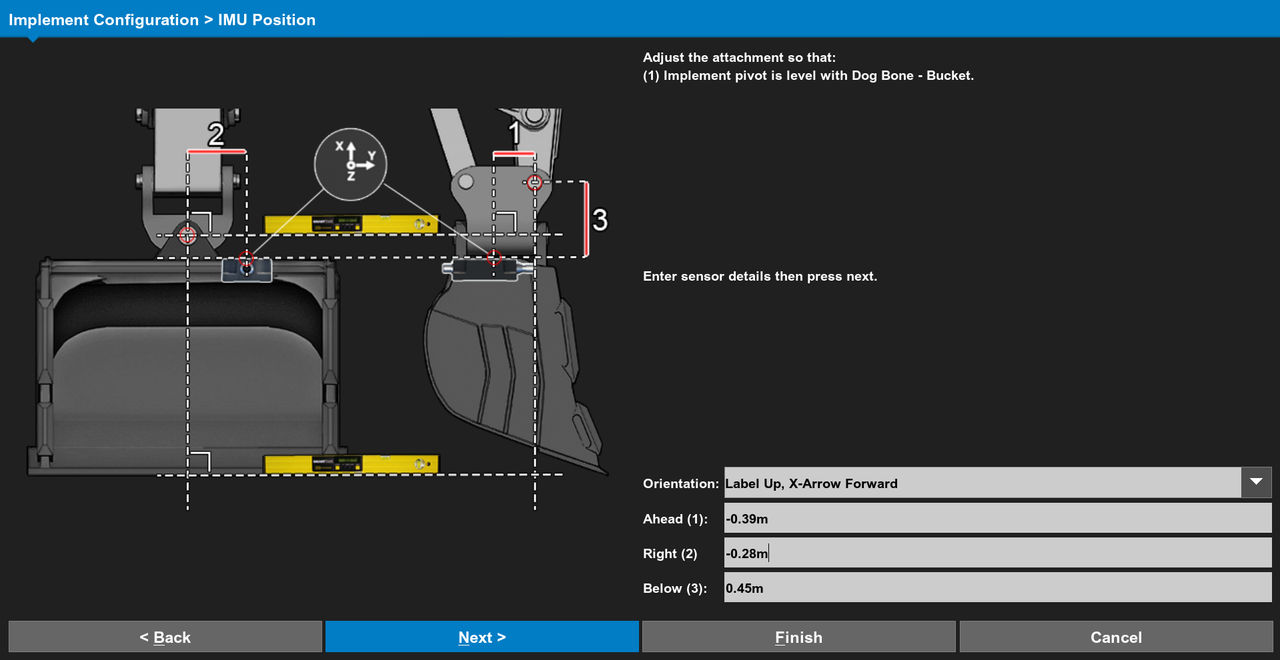
- Select Calibrate on the Hitch Sensor Calibration screen.
- Select Next. ADDITIONAL INFORMATION:
Figure: Hitch Sensor Calibration 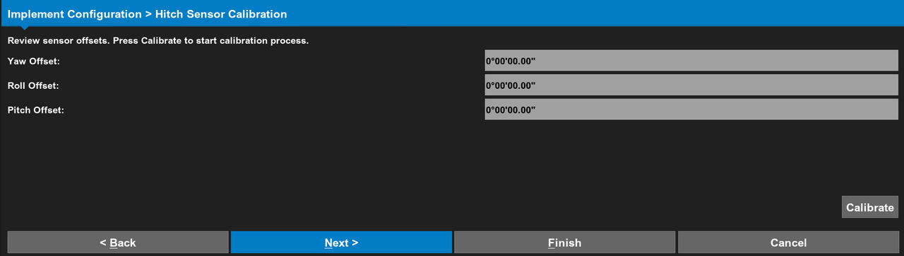
- Measure to get the shape of the implement on the Implement Radius screen:
- Set the implement on the ground with the base level.
- Make an estimate for the center of the implement curvature. Then, release a plumb bob from that point to the ground.
- Measure that distance and enter it in Base Length (1).
- Measure the implement radius from the same point to the curved edge of the implement.
- Enter that distance in Base Radius (2).
- Select Next.ADDITIONAL INFORMATION:
Figure: Implement radius 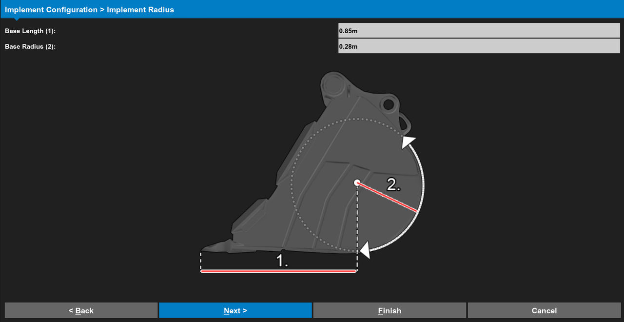
- Select Calibrate on the Implement Calibration screen.ADDITIONAL INFORMATION:
Figure: Implement calibration 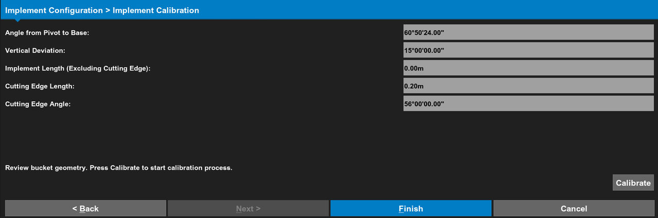
- Curl the implement until the edge is directly below the pivot pin.
- Release a plumb bob from the pivot pin to the edge of the implement.
- Select Capture.ADDITIONAL INFORMATION:
Figure: Implement pivot to edge 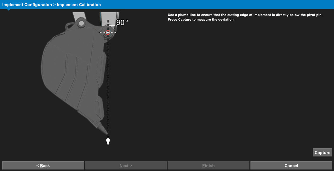
- Set the implement on the ground with the base level.
- Select Capture.ADDITIONAL INFORMATION:
Figure: Implement base level 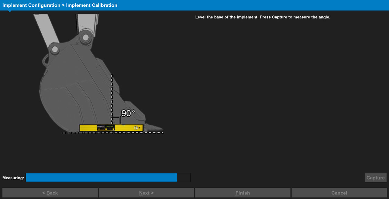
- Curl the implement to make the teeth of the implement level.
- Select Capture.ADDITIONAL INFORMATION:
Figure: Implement wear level 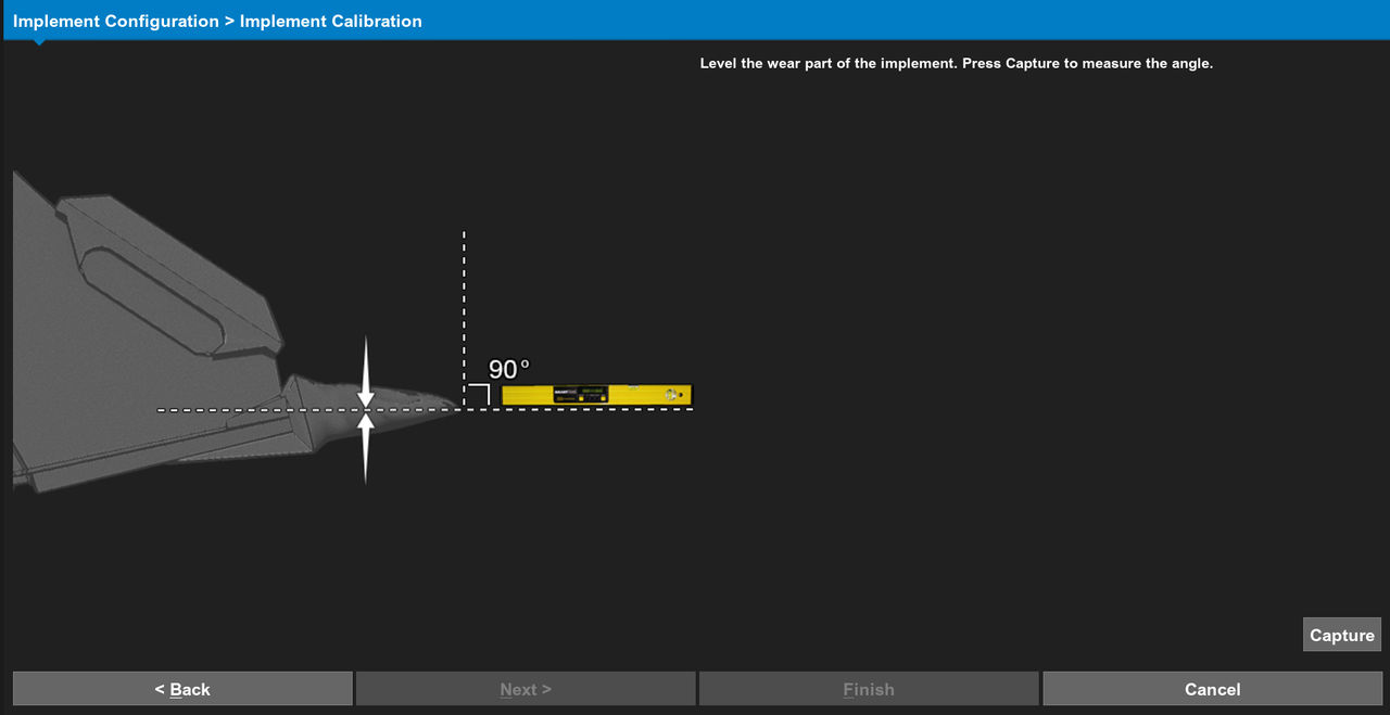 The Implement Calibration screen shows with all fields completed.
 - Select Finish.ADDITIONAL INFORMATION:
Figure: Finish calibration 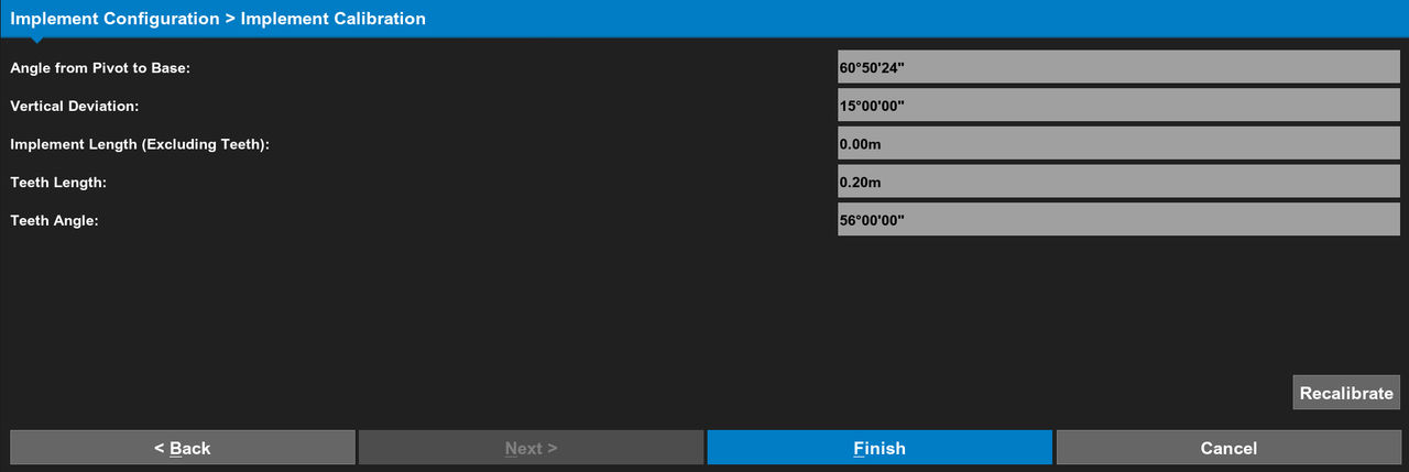 If necessary, select Recalibrate.
Next:
CAT attachments
myTopcon NOW! support
Take your Topcon experience to the next level with myTopcon NOW! This platform is a self-service tool for your desktop or mobile device.