After the MC-Mobile CTL system is calibrated, the Elevation Control button displays cut/fill readings and the cut/fill offsets for the elevation of the blade or implement.
The Elevation Control button also indicates the status of the connected sensor with graphics, informational messages, and colors. Refer to 3D-MC Software v15 User Manual for Construction Systems (P/N 1013515-01 on myTopconNOW!
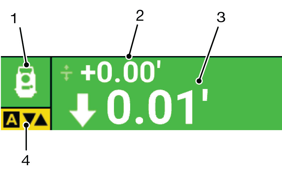
1 | Elevation Sensor Type and Status | Shows GNSS status with green indicating suitable for grading; crossed-out icon indicates corresponding receiver is not available; and flashing radio icon (3-10 seconds) indicates weak radio signal. |
2 | Set Point | Shows the current set point or vertical offset to the design surface. Use set points to maintain an offset to the design surface, such as trimming overbuilt areas to grade or managing lifts for fill material. |
3 | Cut/Fill | In 3D control, shows the current Cut/Fill reading or distance from finish grade. The number continuously updates according to the elevation difference between the cutting edge and the design surface. |
4 | AUTO Indicator | AUTO with yellow background indicates Automatic Control is engaged. If AUTO shows in red letters with a line through it, the elevation is outside of working parameters and feature is unavailable. |
Elevation Control Button Background | Background color indicates sensor status:
|