After the 3D-MC CTL system is calibrated, the Slope Control button displays cut/fill readings and the cut/fill offsets for the elevation of the blade or implement. The Elevation Control button also indicates the status of the connected sensor with graphics, informational messages, and colors.
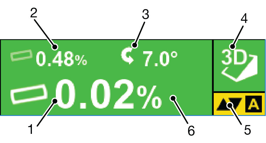
| 1 | Design cross slope | Current cross slope of the design surface, perpendicular to heading of CTL. |
| 2 | Blade slope | Blade graphic on Slope Control button tilts depending on surface of design slope. |
| 3 | Blade rotation | Current blade position as CW or CCW. |
| 4 | Type of control | Indicates whether 3D or 2D control is active. |
| 5 | AUTO indicator | AUTO with yellow background indicates Automatic Control is engaged. If AUTO shows in red letters with a line through it, the elevation is outside of working parameters and feature is unavailable. |
| 6 | Slope Control button background | Background color indicates sensor status:
|