- Park the machine on a planar surface.
- Make sure that the machine boom arms are all the way on the boom stops on the frame of the machine. It can be necessary to tilt the hitch plate back or lift up the sides of the grader blade. This makes sure that the boom stops are reached.
- Lift the blade in the air to let the front wheels of the attachment contact the rigid surface.
- Use the hitch plate forward tilt to apply light down pressure to the attachment wheels. Do not let the blade touch the surface. The wheels must contact the surface but can move when force is applied.
- For Level Best and Bobcat, side-shift the blade to its center position. There are white indication lines that show when the blade is centered. ADDITIONAL INFORMATION:
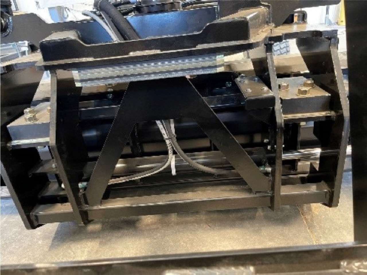
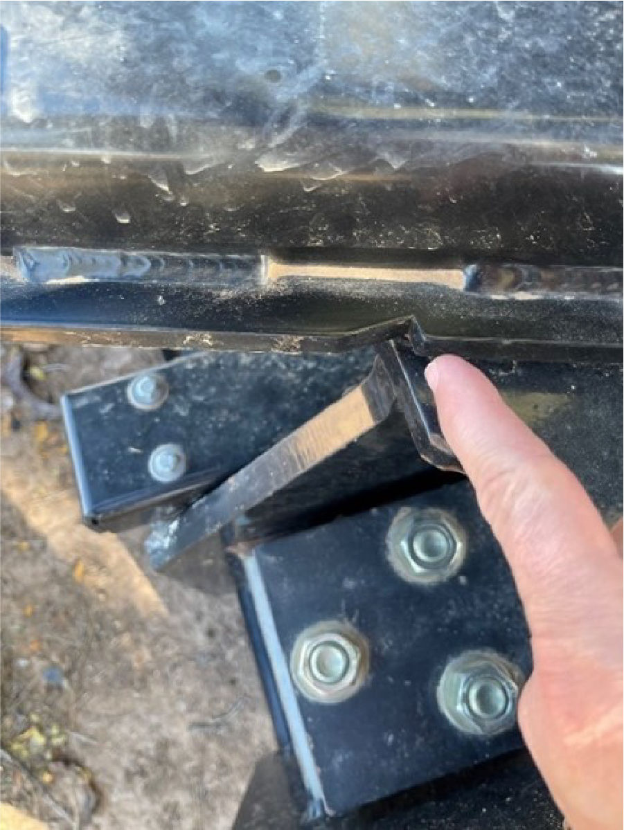
- Turn the blade until it is fully square:ADDITIONAL INFORMATION:
- For Level Best - Examine the 90-degree notches on top of the A-frame circle. As the blade turns, the bottom section lines up with the 90-degree notches on top. Make sure that the left and right sides are fully aligned with the notch.
- For other grader blades - Measure the left and right rotation cylinders from the front of each cylinder barrel to a fixed identical point on each piston rod.
- Select the Main Menu icon to show the Settings menu.
- Set the grader blade attachment as the active attachment.
- Select . The Calibration (1) screen shows.
- Complete the onscreen instructions carefully. Refer to Step 3 through 5 for guidance.
- Select Next. The Calibration (2) screen shows.ADDITIONAL INFORMATION:
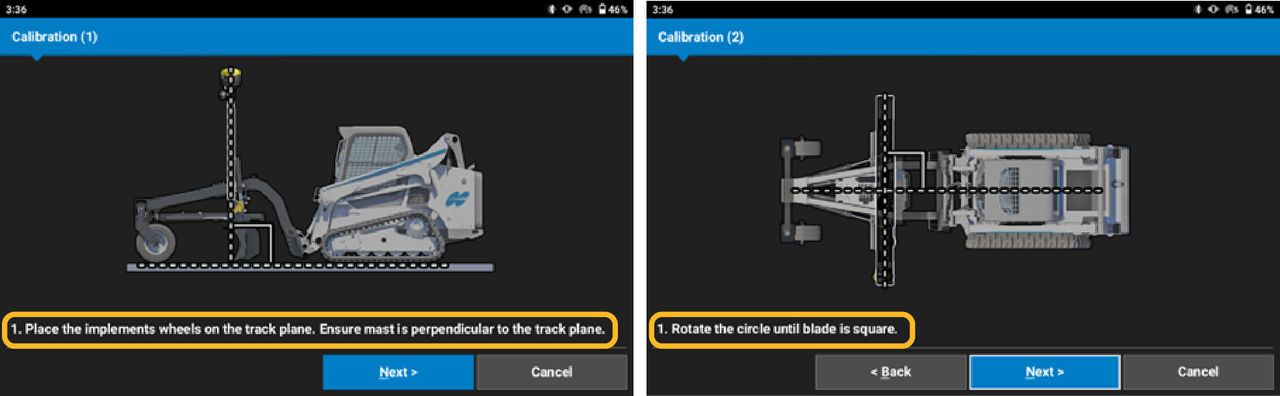
- Complete the onscreen instructions carefully. Refer to Step 5 for guidance.
- Select Next.
- Lift or lower the blade as necessary to match the calibrated cross slope of the machine body. Make sure that it is not necessary to move more than a small amount.ADDITIONAL INFORMATION:
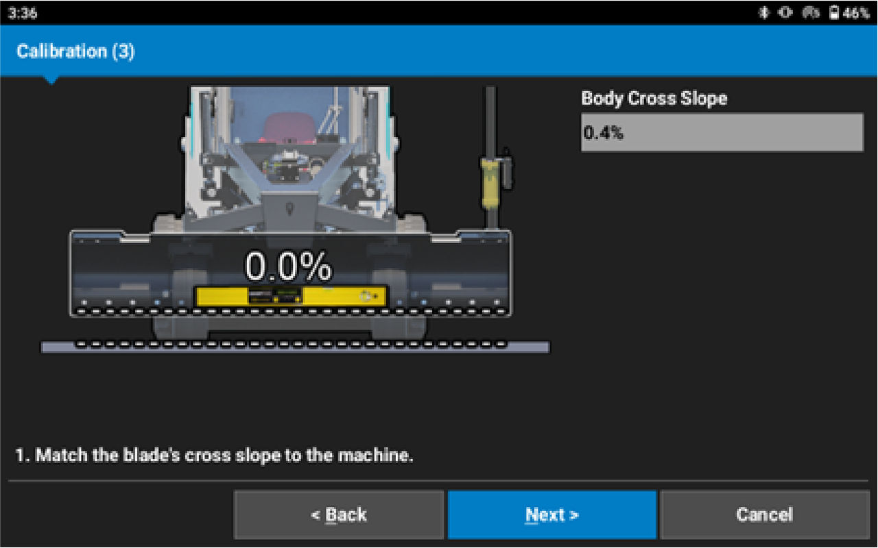
- Select Next. ADDITIONAL INFORMATION:
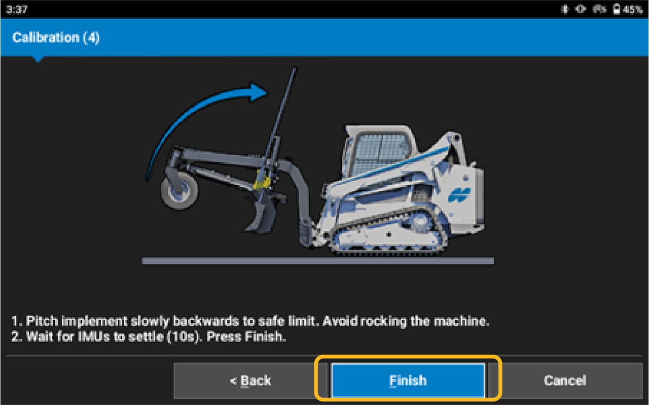
- Carefully tilt the hitch coupler plate back towards the machine. Do not lift the boom arms because this causes calibration failure. Tilt back slowly to prevent the machine or attachment from rocking. Tilt back until cylinder moves a minimum of 80% or to a safe permitted limit.
- Wait 10 seconds for the IMU to settle.
- Select Next.ADDITIONAL INFORMATION:
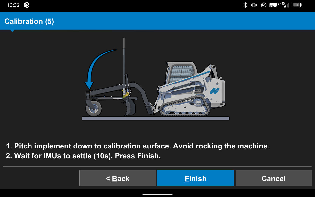
- Carefully tilt the hitch coupler forward back down to the calibration surface.
- Select Finish.
myTopcon NOW! support
Take your Topcon experience to the next level with myTopcon NOW! This platform is a self-service tool for your desktop or mobile device.