- Select the cable routing.
- Make sure to pull loose 5 m M12 cable through the boom access slot until the outer machine. This cable follows the boom arm, along the hydraulic hoses, and connects to a tee near the bayo to M12 Y cable. The bayo to M12 Y cable installs onto the machine bulkhead near the hydraulic coupler connections.
- Look at the movement range for all moving parts when you plan the routing of the cable. Make sure that there is sufficient clearance for the connection of the sensor cable. For example, in a hydraulic hose for protection. Also, there must be clearance for the strain relief plates and the cover. ADDITIONAL INFORMATION:These pictures show the possible locations for the hitch sensor.
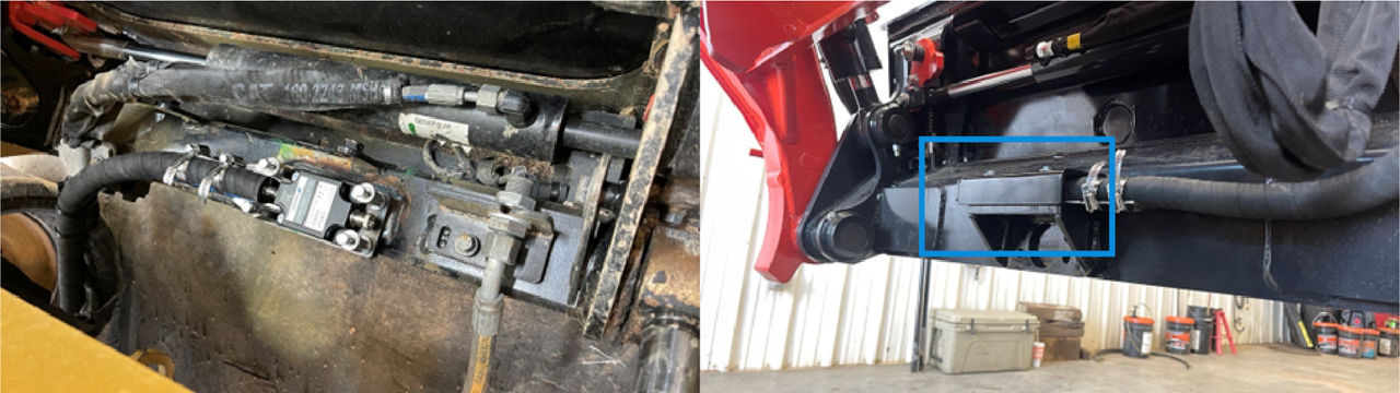
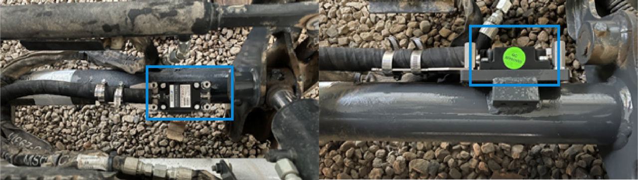 These orientations are available for the TS-i4 hitch sensor.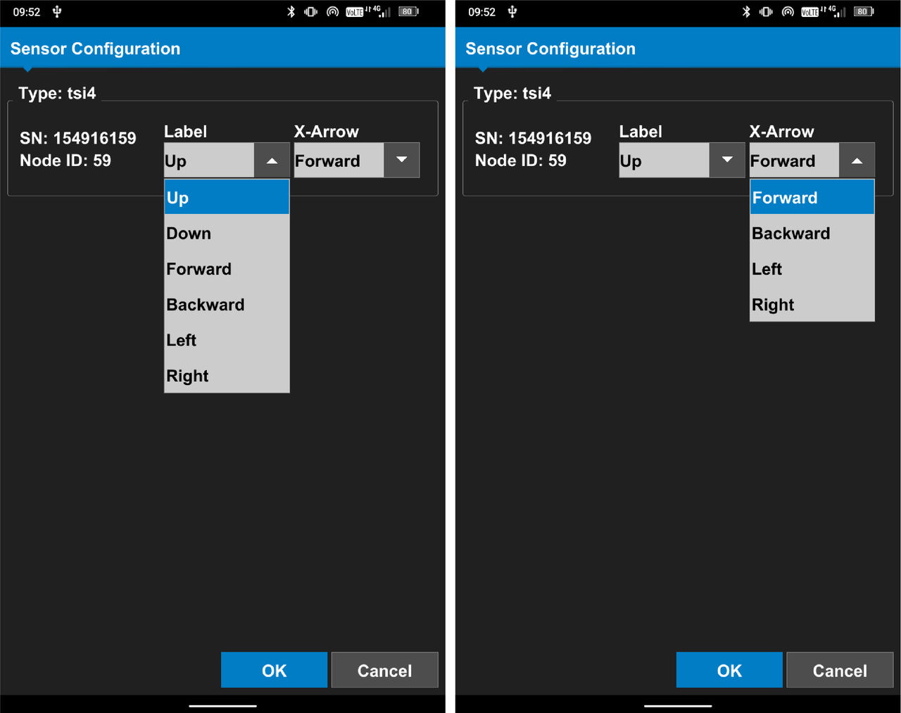
- Tilt the hitch plate of the machine until the cross member is level, parallel to the long axis of the machine.
- Disconnect the negative battery terminal on the machine.
- Weld the plate onto the frame. Follow the same guidelines used to weld the previous plates. Refer to the related topic TS-i4 body sensor installation. ADDITIONAL INFORMATION:
Figure: Hitch sensor weld pad 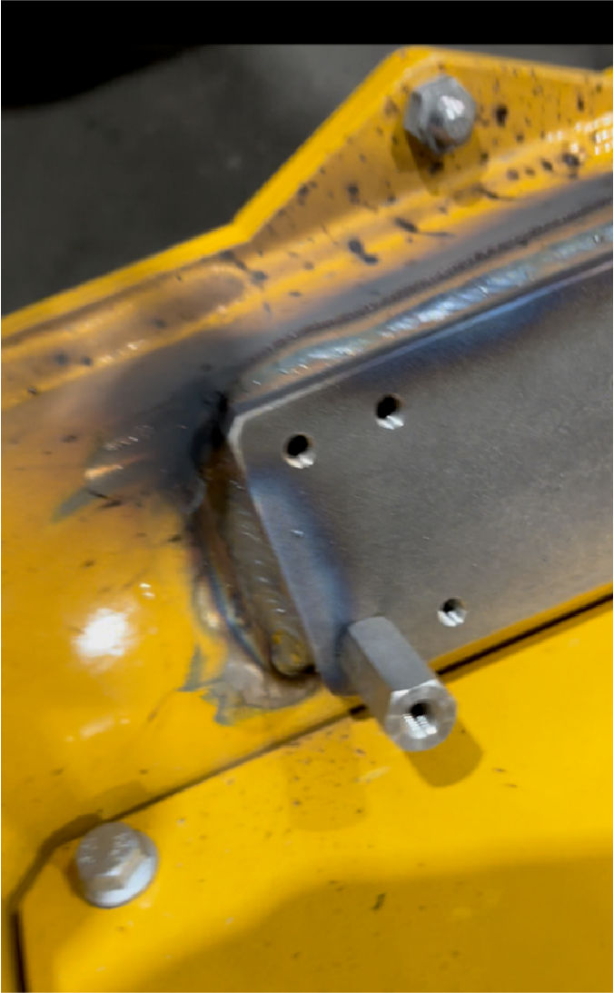
- Put together the hitch sensor assembly. Do not install the cover until after setup.
- Add a dust cap.
- Connect an M12 cable and a terminator to the sensor.
- Calculate the length of protective hydraulic hose that is necessary to give protection for the M12 cable.
- Cut the protective hydraulic hose to the necessary length.
- Put the cable through the hydraulic hose and attach it to the strain relief plate with two hose clamps.ADDITIONAL INFORMATION:
Figure: Hitch sensor secured 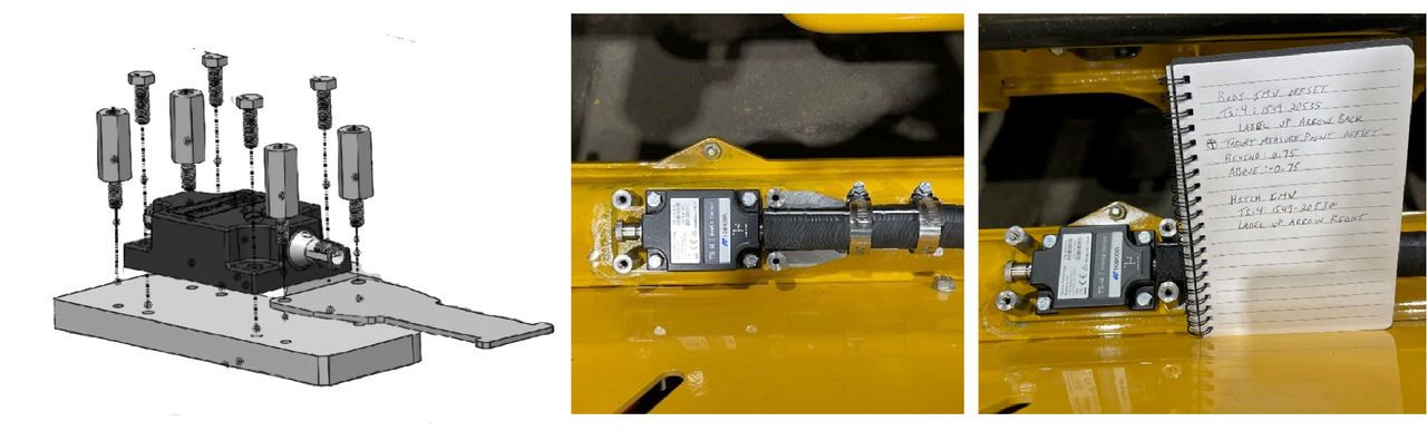
- Make sure that the strain relief lets full travel and pitch of the hitch plate. Slowly tilt the hitch plate in and out to the cylinder travel limits and make all necessary adjustments to the P clamps and strain relief.
- Make sure that the cable which runs back to the tee near the machine bulkhead is wire-loomed for protection. Make sure that the boom arm does not pinch or pull on the tee or bulkhead connector when the hitch plate is tilted.
- Return the hitch plate until it is level, parallel to the long axis of the machine.ADDITIONAL INFORMATION:Note: Do not install the cover until machine measurements and calibration are completed.
Previous:
Bulkhead installation
Next:
Attachment installation
myTopcon NOW! support
Take your Topcon experience to the next level with myTopcon NOW! This platform is a self-service tool for your desktop or mobile device.