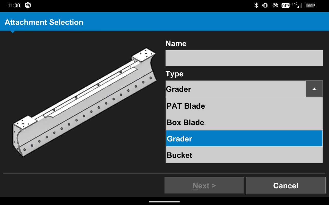
- Select Grader from the Type list.
- Select the attachment Make/Model.ADDITIONAL INFORMATION:
- Select Next.
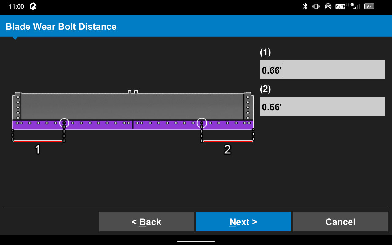
- Complete the onscreen illustrations to measure the right side (1) and left side (2) Blade Wear Bolt Distance.ADDITIONAL INFORMATION:
- Select Next.
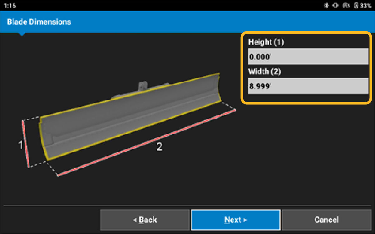
- Measure from the bottom of the cutting edge to the top of the moldboard for blade Height (1).
- Measure from the bottom right blade corner to the bottom left blade corner for blade Width (2).ADDITIONAL INFORMATION:
- Select Next.
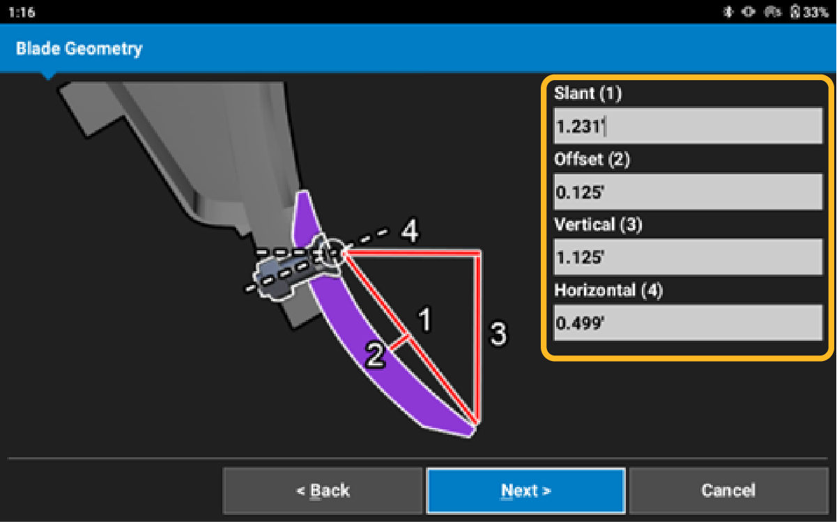
- Put a rigid straight edge on the center of the bolt and the bottom of the cutting edge to measure the cutting edge Slant (1). Measure the distance between the center of the bolt and the bottom of the cutting edge, along the straight edge line.
- Measure from the rigid straight edge line between the center of the bolt and the bottom of the cutting edge to measure the Offset (2).
- Measure from the bottom of the cutting edge to the center of the bolt to measure the Vertical (3).ADDITIONAL INFORMATION:The Horizontal (4) measurement is calculated and shows based on the measurements for Slant, Offset, and Vertical.
- Select Next.
- Select Yes to update the blade wear values.
- Select Mast Type. Select Z-Stack for one GR-i3, and then select GR-i3. For RP-i3, select Z-Stack, and then select RP-i3.ADDITIONAL INFORMATION:
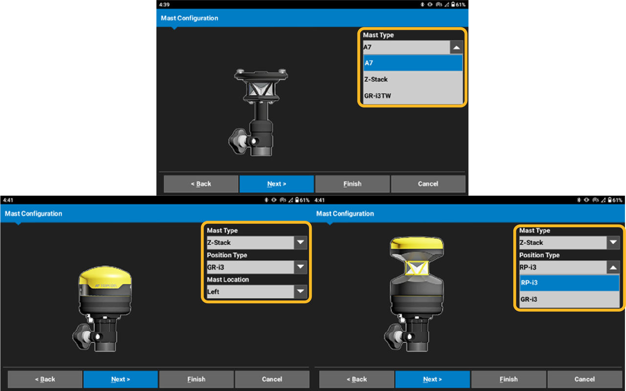 Note: CAT Mastless Grader blade and Box blade will not display Mast Configuration and Mast Dimensions.
 - Select theor Right side from the operator’s seat.ADDITIONAL INFORMATION:
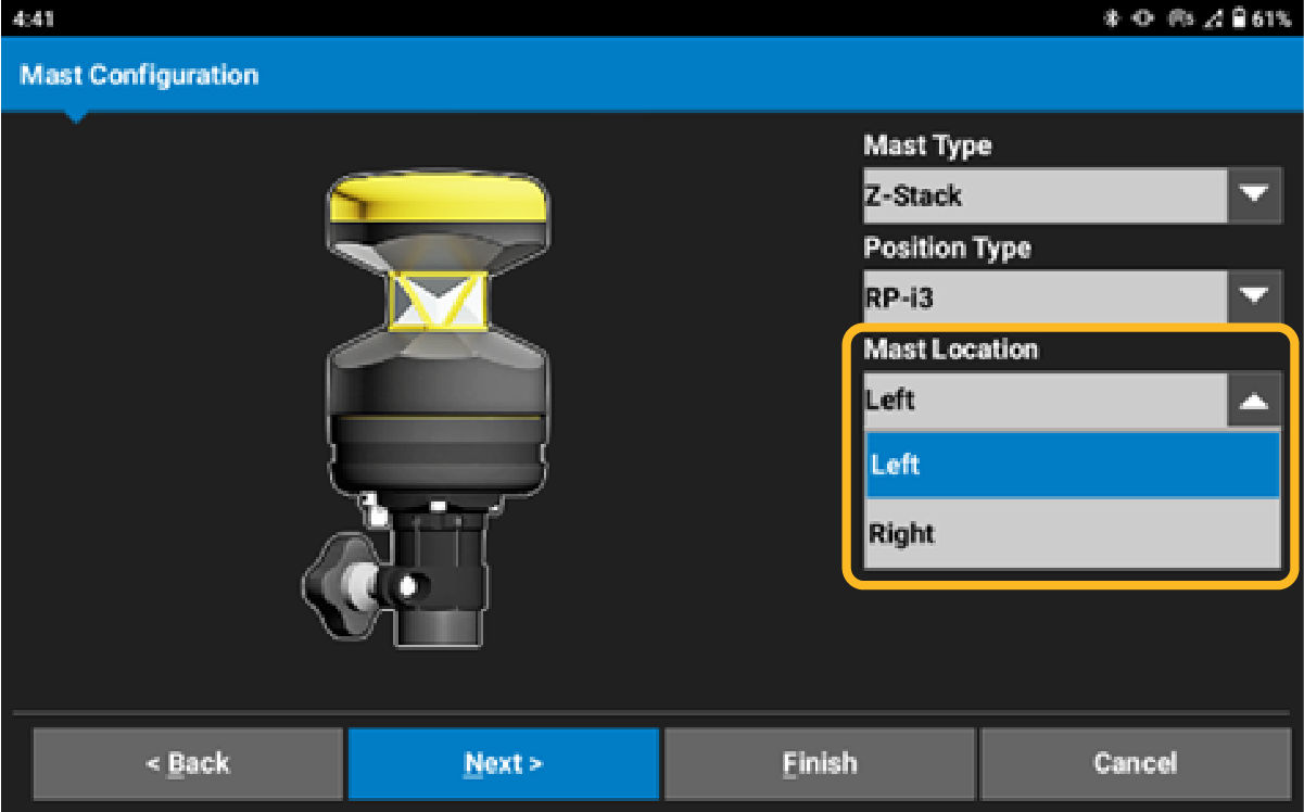
- Select Next.
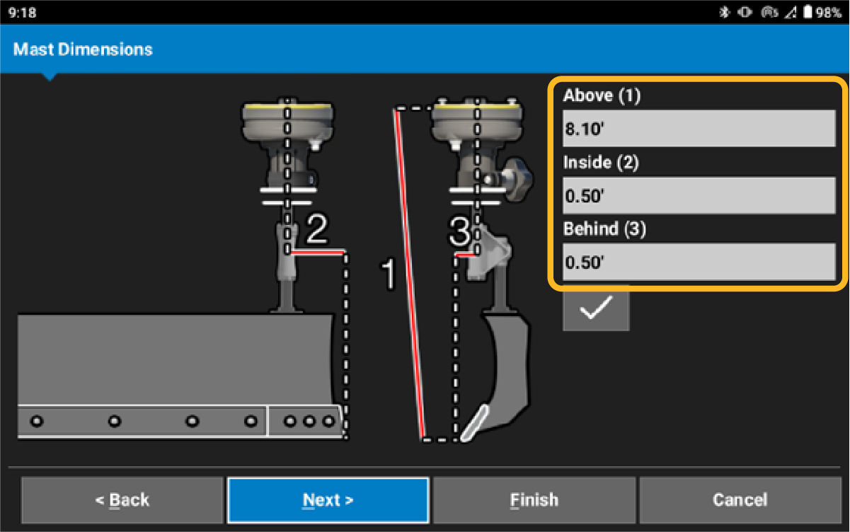
- Measure from the snap point of the GR-i3 or the center of the prism to the bottom of the cutting edge for mast Above (1) measurement.
- Measure from the bottom, left or right based on mast placement, outside of the cutting edge to the center of the GR-i3 or prism for mast Inside (2) measurement.
- Measure from the bottom of the cutting edge to the center of the GR-i3 or prism for mast Behind (3) measurement.ADDITIONAL INFORMATION:
- Select Next.
- Assign the TS-i4 Hitch sensor. Select the Sensor ID drop-down menu. Use the recorded information from the installation. Select the Sensor ID.
- Select the Wrenchicon and select the TS-i4 Hitch sensor IMU orientation.ADDITIONAL INFORMATION:
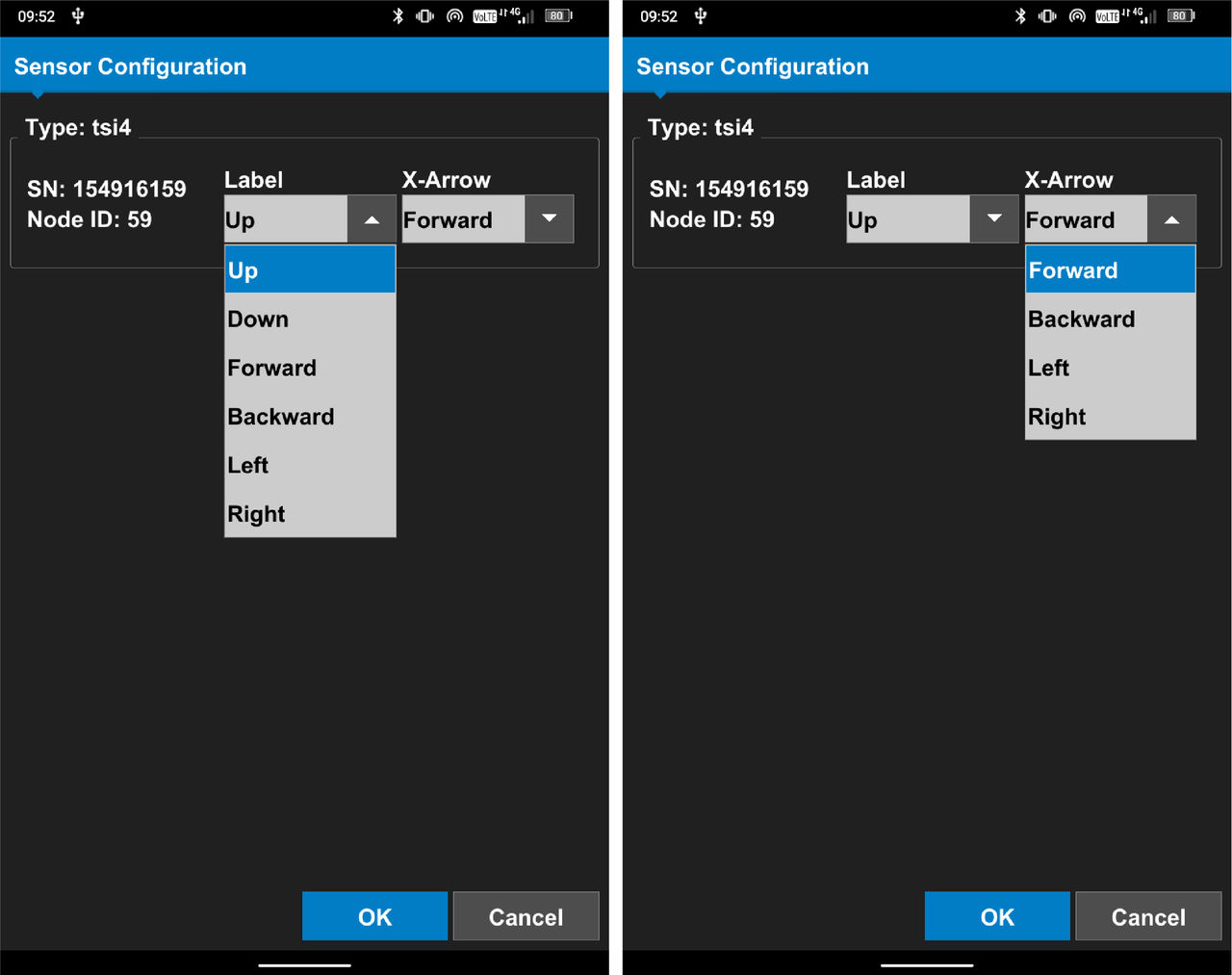
- Select OK.ADDITIONAL INFORMATION:

- Measure from the center of the right side hitch pivot pin to the center of the IMU crosshair for IMU Above (1)measurement.
- Measure from the center of the right side hitch plate pivot pin to the center of the IMU crosshair for IMU Inside (2)measurement.
- Measure from the center of the right side hitch plate pivot pin to the center of the IMU crosshair for IMU Behind (3)measurement.ADDITIONAL INFORMATION:Note: The TS-i4 Hitch sensor is usually behind the hitch plate pivot pin, but some machines can have it forward. If the TS-i4 Hitch sensor is ahead of the hitch plate pivot pin, enter the measurement with a negative value.
- Select Next.ADDITIONAL INFORMATION:Note: It is necessary for CAT Mastless Grader blade and Box blade configurations to have another measurement. To set up a Masted configuration, go to the Blade Pivot Point measurements (Step 35).
- Assign the TS-i4 C-Frame sensor. Select the Sensor ID drop-down menu. Use the recorded information from the installation. Select the Sensor ID.
- Select the Wrench icon and select the TS-i4 C-Frame sensor IMU orientation. ADDITIONAL INFORMATION:
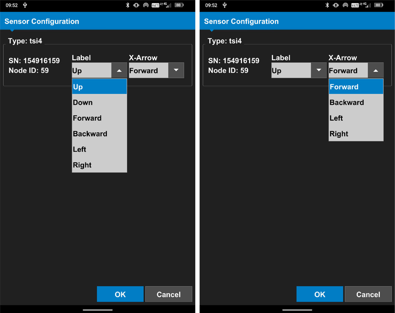
- Select OK.ADDITIONAL INFORMATION:
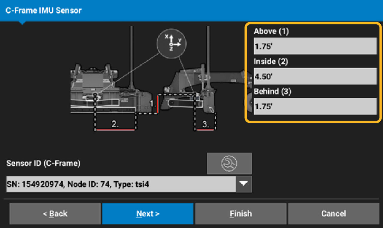
- Measure Above (1), from the track plane to the center of the C-Frame IMU crosshair.
- Measure Inside (2), from the right side blade corner to the center of the C-Frame IMU.
- Measure Behind (3), from the cutting edge to the center of the C-Frame IMU crosshair.
- Select Next.
- Measure Pivot Behind (1), from the cutting edge to the right side hitch plate pivot pin.
- Measure COR Behind (2), from the cutting edge to the blade center of rotation pivot point.ADDITIONAL INFORMATION:
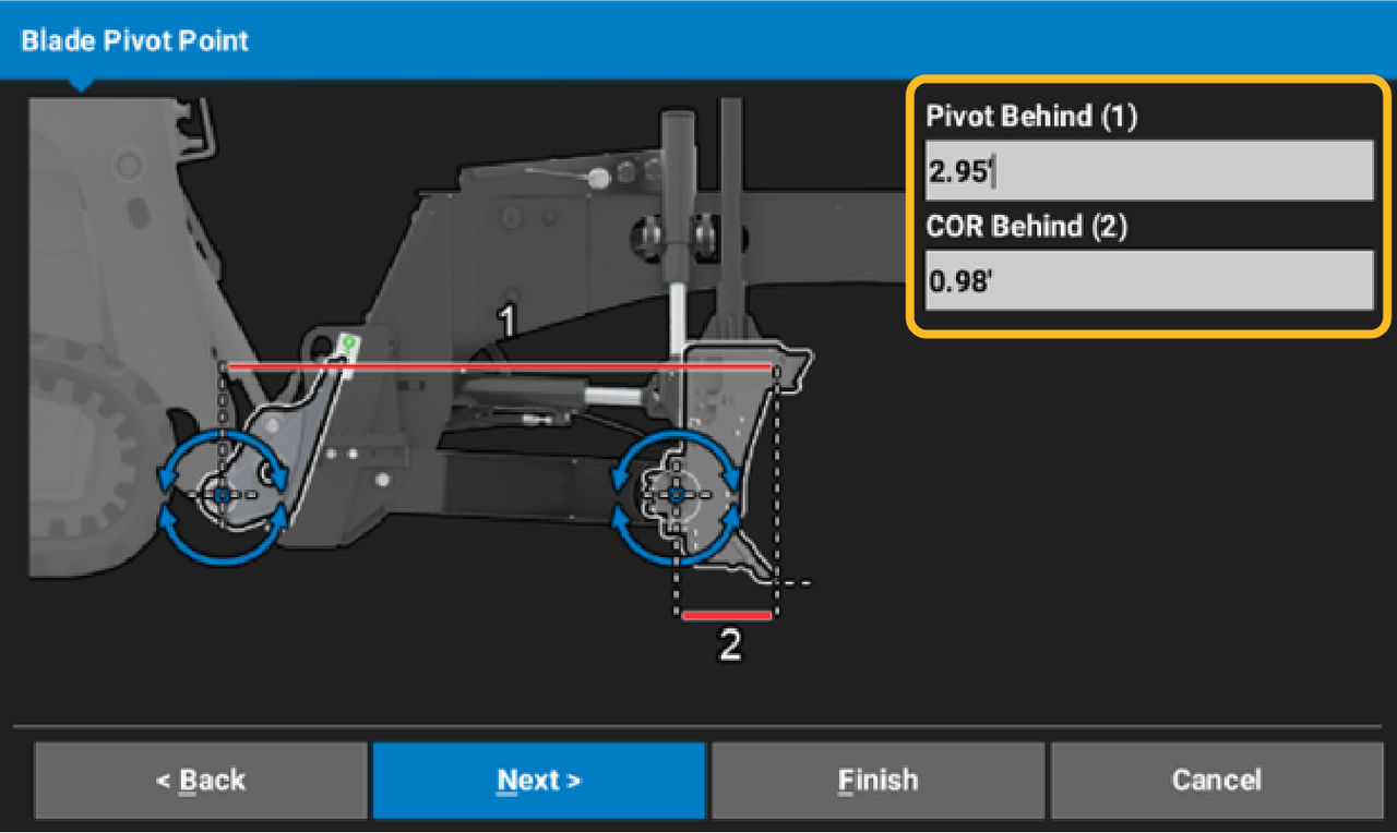
- Select Next.
- Measure C-Frame Behind (1), from the cutting edge to the C-Frame pivot pin.
- Measure C-Frame Above (2), from the track plane to the C-Frame pivot pin.ADDITIONAL INFORMATION:
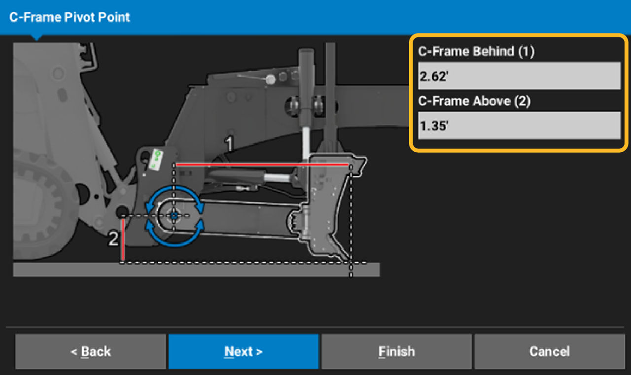
- Select Next.
- Assign the TS-i4 Blade sensor. Select the Sensor ID drop-down menu. Use the recorded information from the installation. Select the Sensor ID.
- Select the Wrench icon and select the TS-i4 Blade sensor IMU orientation.ADDITIONAL INFORMATION:
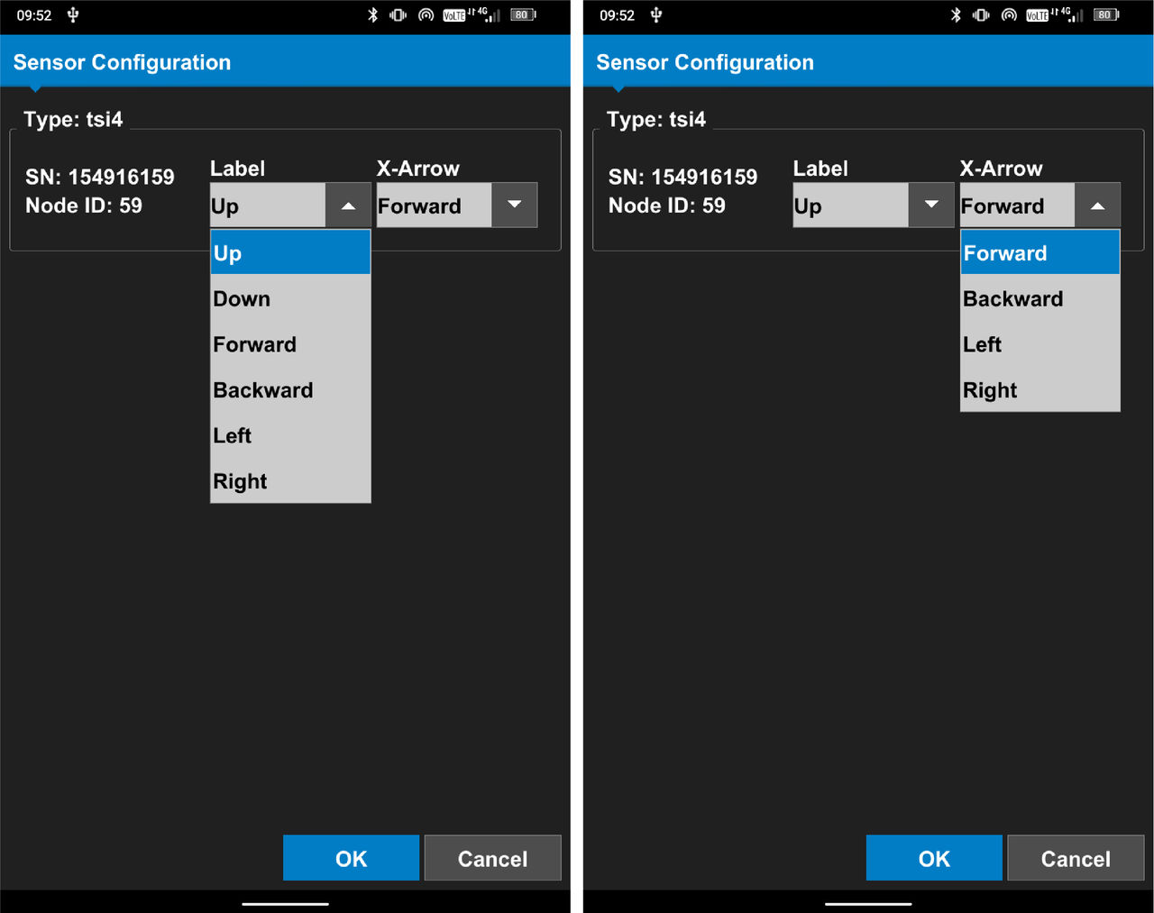
- Select OK.ADDITIONAL INFORMATION:
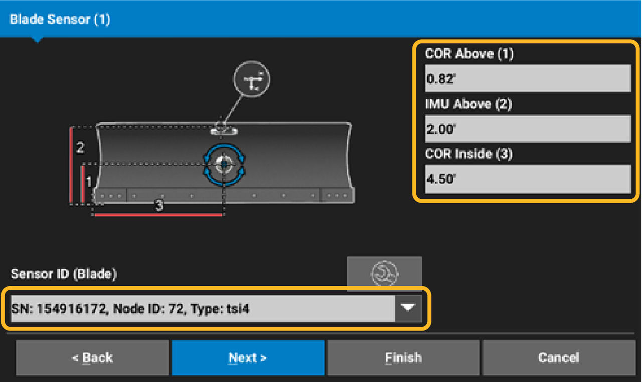
- Measure COR Above (1), from the track plane to the center of the blade rotation point.
- Measure IMU Above (2), from the track plane to the center of the Blade IMU crosshair.
- Measure COR Inside (3), from the right blade corner to the center blade rotation point.
- Select Next.
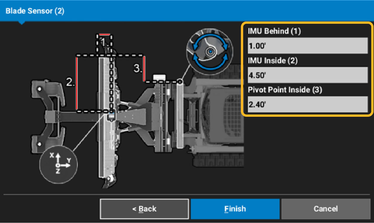
- Measure IMU Behind (1), from the cutting edge to the center of the Blade IMU crosshair.
- Measure IMU Inside (2), from the right side blade corner to the center of the Blade IMU crosshair.
- Measure Pivot Point Inside (3), from the right side blade corner to the center of the right side hitch plate pivot pin.ADDITIONAL INFORMATION:
- Select Finish.
- Select to set as Active Attachment or not.
- Continue to do the IMU calibration. Refer to the related topic for instructions.
myTopcon NOW! support
Take your Topcon experience to the next level with myTopcon NOW! This platform is a self-service tool for your desktop or mobile device.