Looking for your apps? Click the account icon in the upper right corner of the page.
2D body measurements
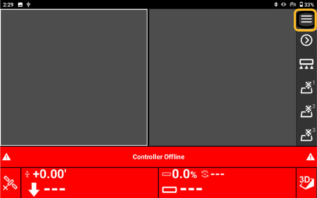
Select the Main Menu icon.
ADDITIONAL INFORMATION:
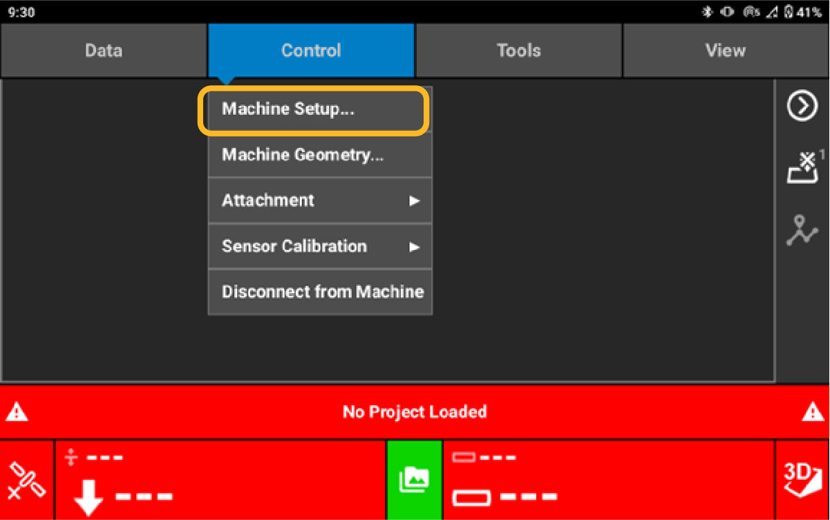
Select ControlMachine Setup.
ADDITIONAL INFORMATION:
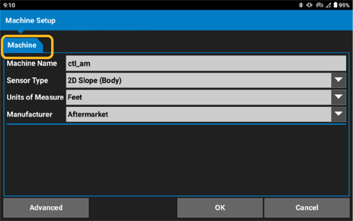
Select a Machine Name, Sensor Type, and Units of Measure.
ADDITIONAL INFORMATION:
Select the Manufacturer.
ADDITIONAL INFORMATION:
Note: The manufacturer selection applies manufacturer-specific joystick functions when Non-CAN box blades are used.
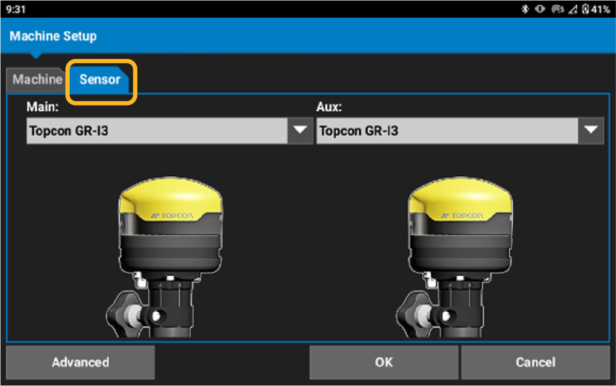
Select Sensor if 3D Position Sensor (Body) was selected as the Sensor Type.
ADDITIONAL INFORMATION:
Select the Main and Aux sensor types.
Select OK.
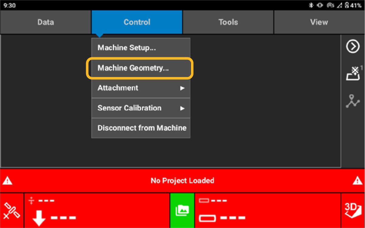
After Machine Setup is completed, select ControlMachine Geometry.
ADDITIONAL INFORMATION:
Note: Get the measurements to the center of the CTL hitch plate pivot pin on the right side of the machine. The right side of the machine is the operator’s right when in the cab.
Note: The body IMU must have been transposed to a measurable point with offset numbers to add to the measurement values from your target point. Refer to the related topic 2D Body installation.
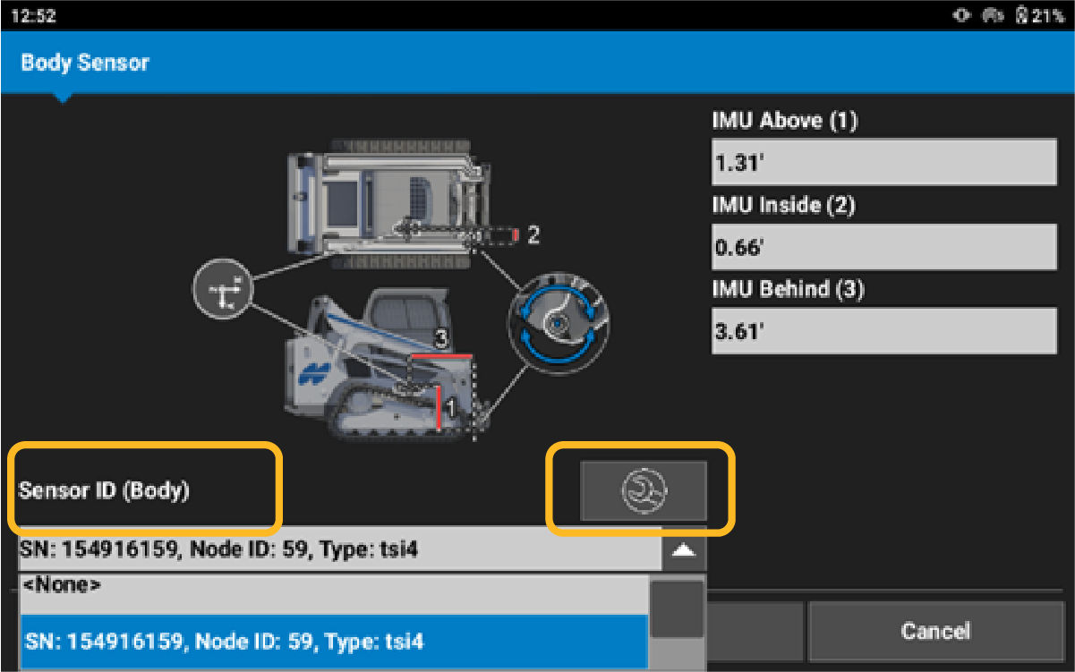
Assign the TS-i4 body sensor from the Sensor ID (Body) list. Use the recorded information from the installation. Select the Sensor ID.
ADDITIONAL INFORMATION:
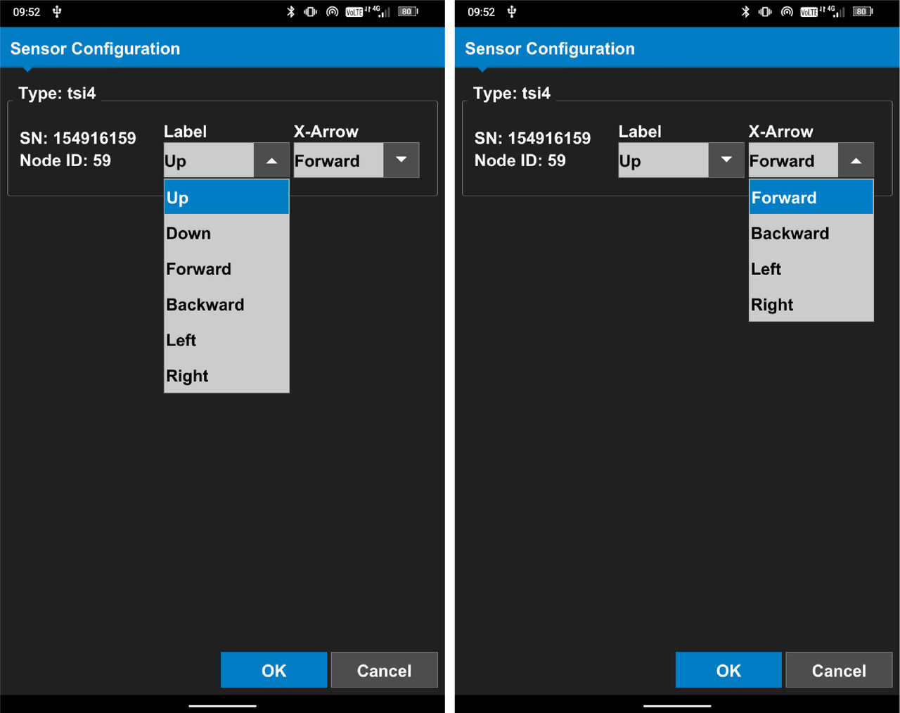
Select the Wrench icon and select the TS-i4 body sensor IMU orientation.
ADDITIONAL INFORMATION:
Select OK.
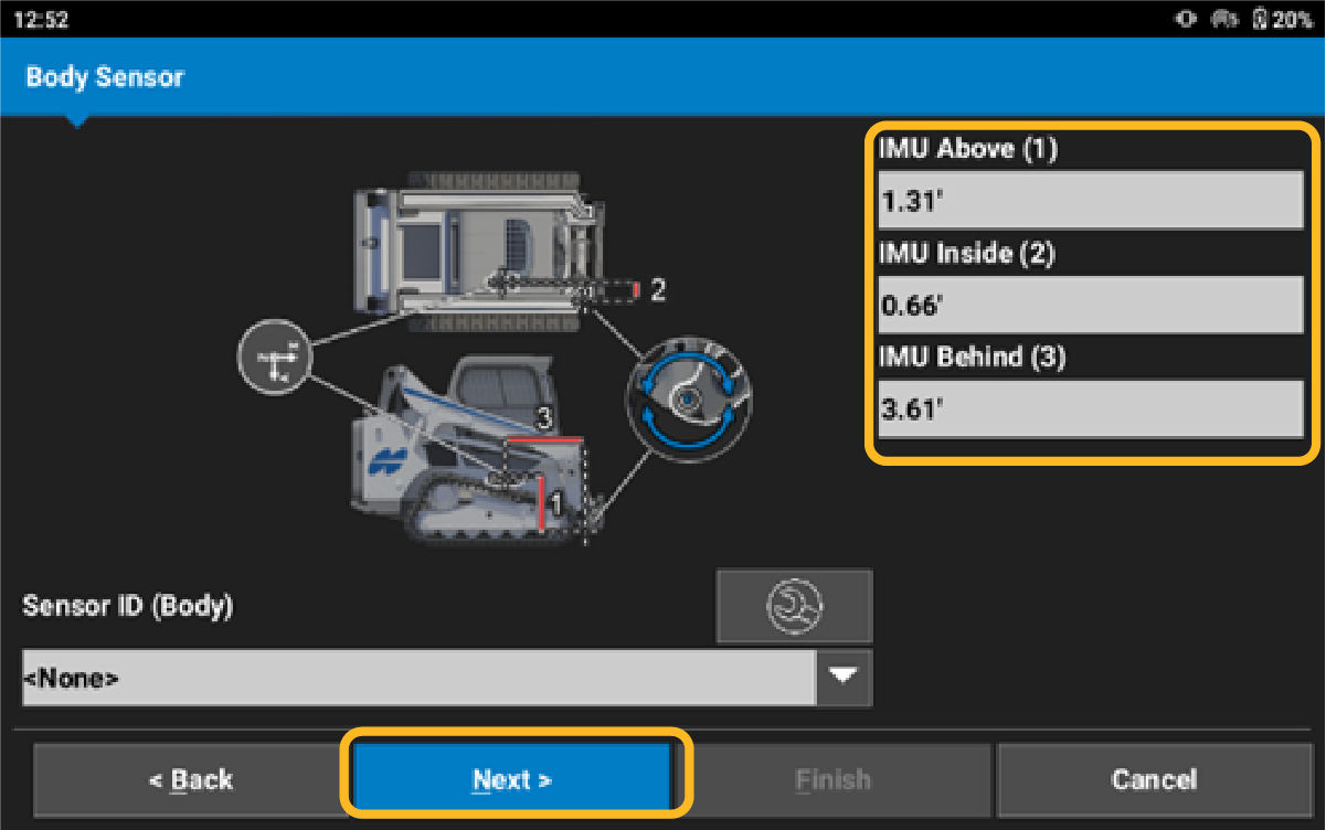
Measure IMU Above (1) from the right side hitch plate pivot pin. Apply offsets to the IMU crosshair to/from the measurable point.
Measure IMU Inside (2) from the right side hitch plate pivot pin. Apply offsets to the IMU crosshair to/from the measurable point.
Measure IMU Behind (3) from the right side hitch plate pivot pin. Apply offsets to the IMU crosshair to/from the measurable point.
ADDITIONAL INFORMATION:
Select Next.
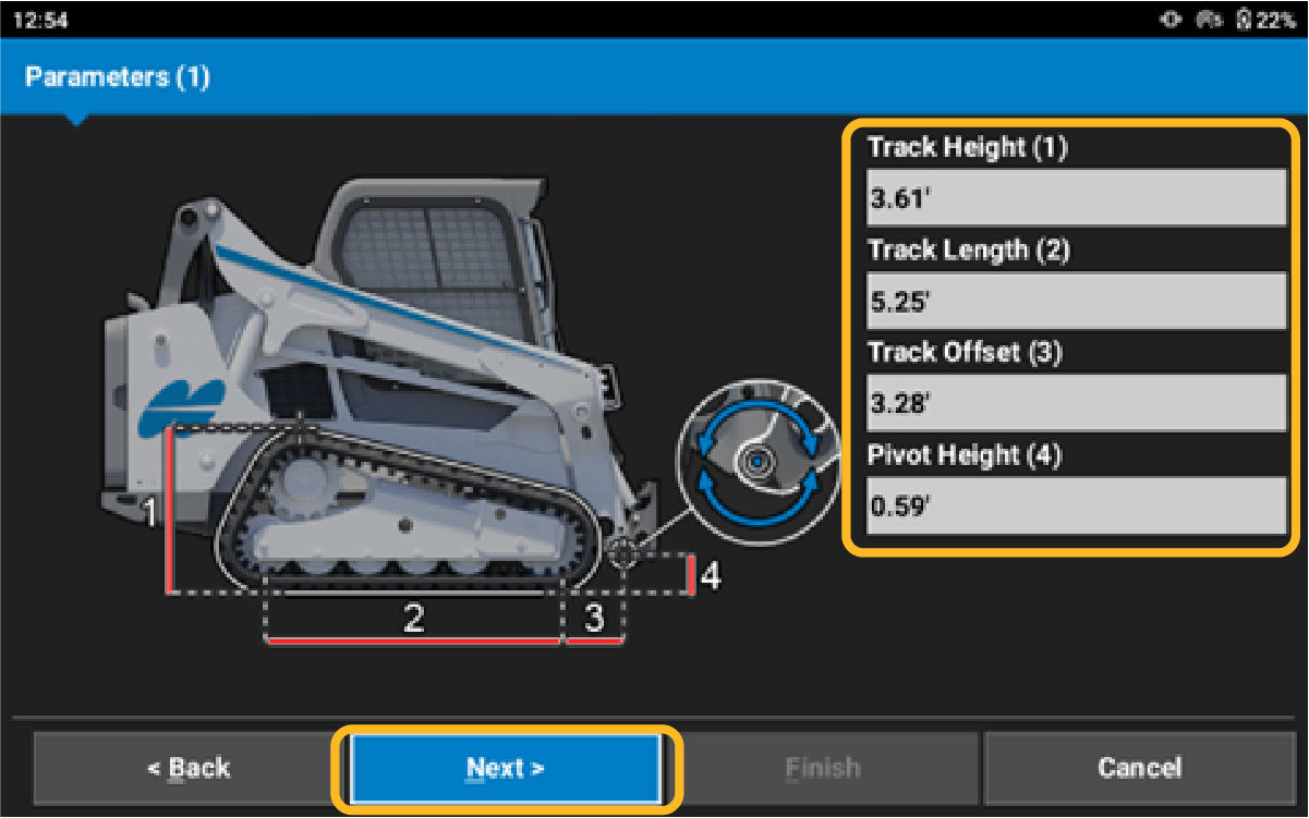
Measure Track Height (1) from the bottom of the track to the top of tallest point on the track.
Measure Track Length (2) from front to back. Only measure the part of the track that contacts the rigid planar surface.
Measure Track Offset (3) from where the front of the track contacts the rigid planar surface to the center of the hitch plate pivot pin.
Measure Pivot Height (4) from the bottom of the track plane on the rigid planar surface, to the center of the right side hitch plate pivot pin.
ADDITIONAL INFORMATION:
Select Next.
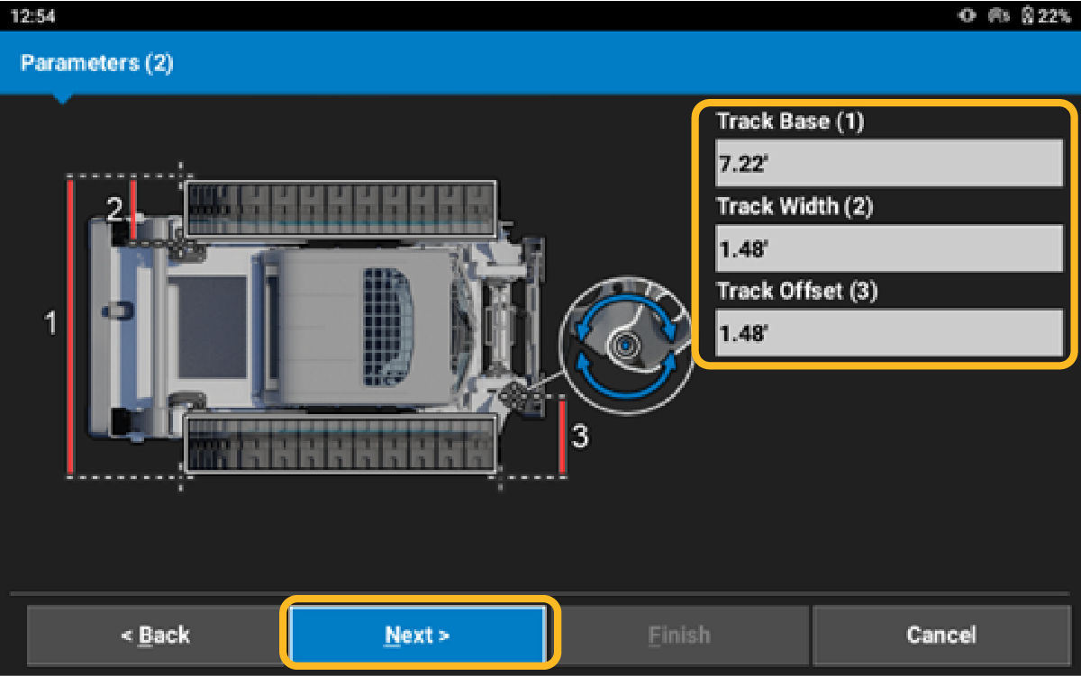
Measure Track Base (1) from the outside track left to the outside track right.
Measure overall left Track Width (2).
Measure Track Offset (3) from the outside of the right track to center of the right side hitch plate pivot pin.
ADDITIONAL INFORMATION:
Select Next.
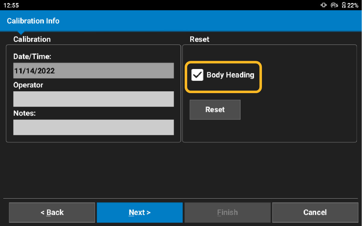
Enter an Operator name. If it is necessary, enter Notes. Make sure that you select Body Heading Reset for the initial measure-up.
Select Next.
ADDITIONAL INFORMATION:
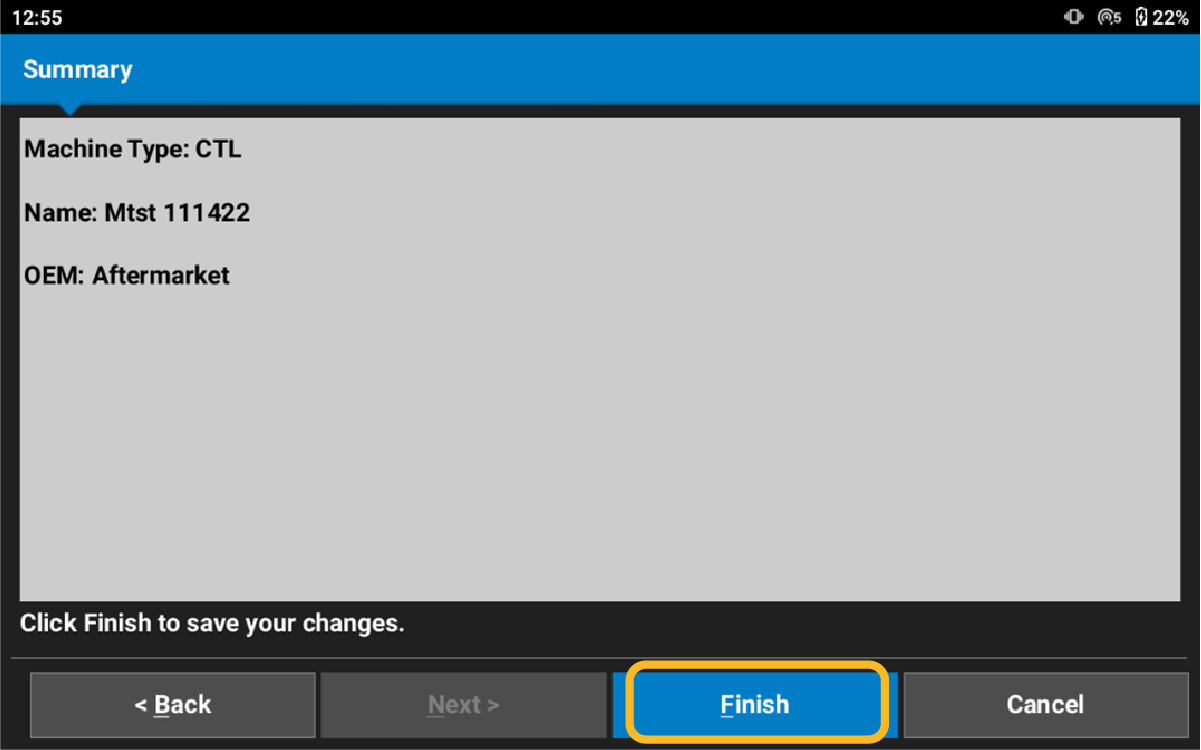
Select Finish.
ADDITIONAL INFORMATION: The 2D body measure-up is completed.

 Note: Get the measurements to the center of the CTL hitch plate pivot pin on the right side of the machine. The right side of the machine is the operator’s right when in the cab.Note: The body IMU must have been transposed to a measurable point with offset numbers to add to the measurement values from your target point. Refer to the related topic 2D Body installation.