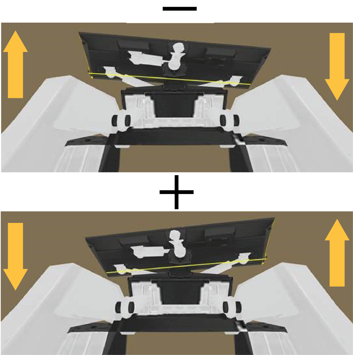
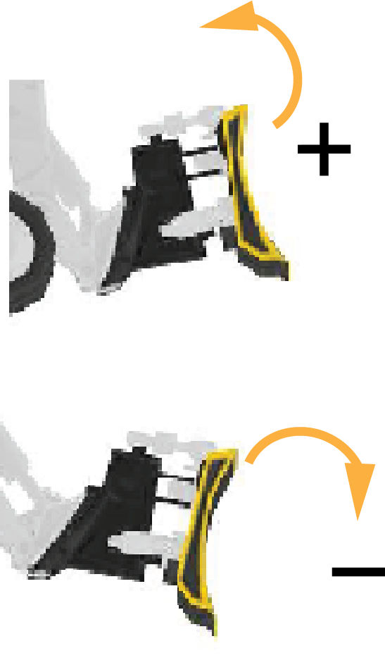
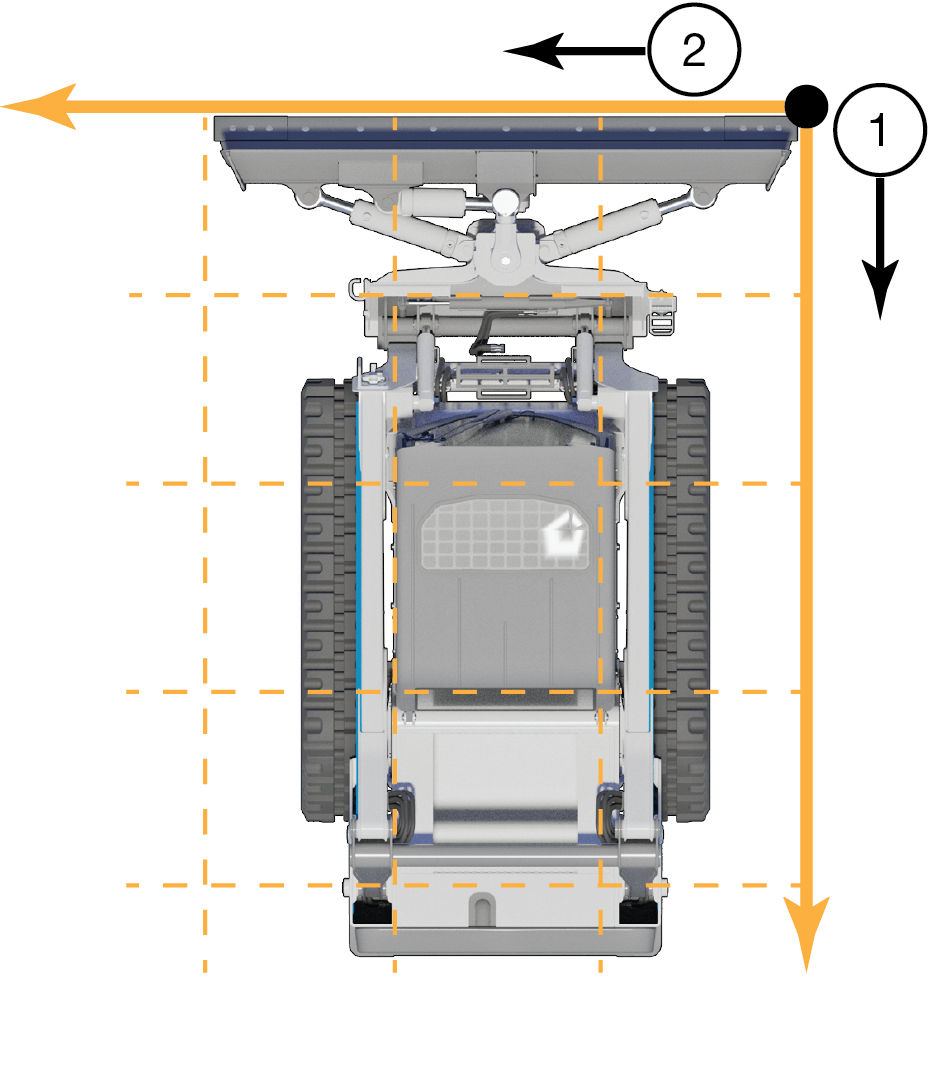
The calculations for cutting edge positions in 3D-MC are based on a CTL coordinate system that is unique and fully internal. Some important rules are applied in these calculations. It is important that all measurements for installation/calibration follow the orientations shown below.
| Term | Orientation |
|---|---|
Behind | The distance from the right blade tip to the device, measured parallel to the centerline of the CTL and towards the rear of the CTL. |
Inside | The offset distance from the right blade tip to the device, measured towards the center of the CTL. |
Above | The height above the cutting edge to a device is measured as the perpendicular (vertical) distance above the plane of the grousers. Always starts from the plane of the grousers, measured vertically up to the device. |
Left/right | The references in 3D-MC to left or right is always from the operator’s perspective, looking forward. |
- Behind
- Inside
- Left
- Right
Make sure the sensors are installed parallel to one of the two main axes.
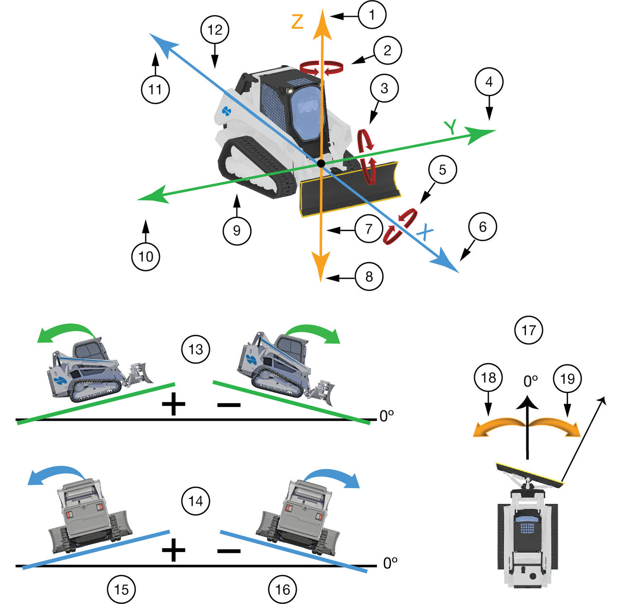
- Up
- Yaw
- Pitch
- Left
- Roll
- Forward
- Z axis/yaw axis
- Down
- Y axis/pitch axis
- Right
- Back
- X axis/roll axis
- Pitch
- Roll
- Counter-clockwise rotation (to left)
- Clockwise rotation (to right)
- Yaw
- Counter-clockwise rotation
- Clockwise rotation