Testing the 3D positional accuracy at the bucket requires three bucket measurements at two boom and stick extensions.
- Install a hub and record the 3D coordinates of the hub using a Total Station and Range Pole or a GNSS Base and Rover.
- Verify that the left, center, and right edge of the bucket match the X, Y, and Z of the Hub.
- Record bucket positions with boom and stick fully extended.ADDITIONAL INFORMATION:
Figure: Bucket positions with boom and stick fully extended 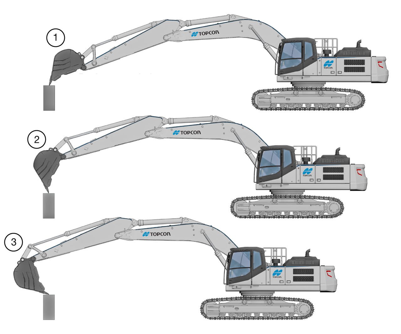
- Bucket Extended
- Bucket Mid-Position
- Bucket Curled
- Record bucket positions with boom and stick retracted.ADDITIONAL INFORMATION:
Figure: Bucket positions with boom and stick retracted 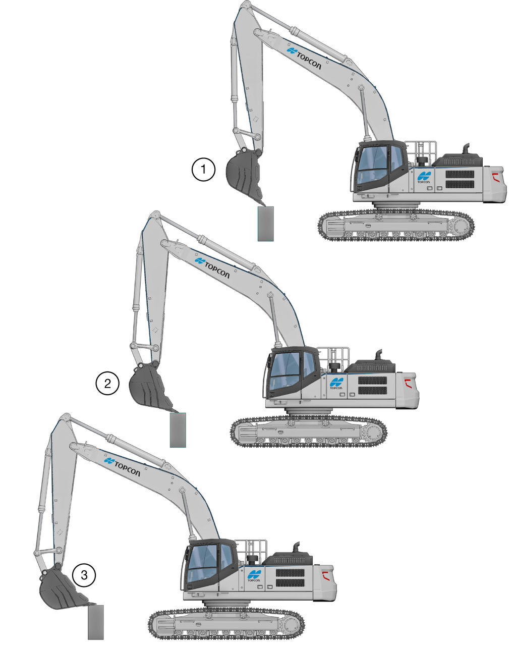
- Bucket Extended
- Bucket Mid-Position
- Bucket Curled
Figure: Positional accuracy 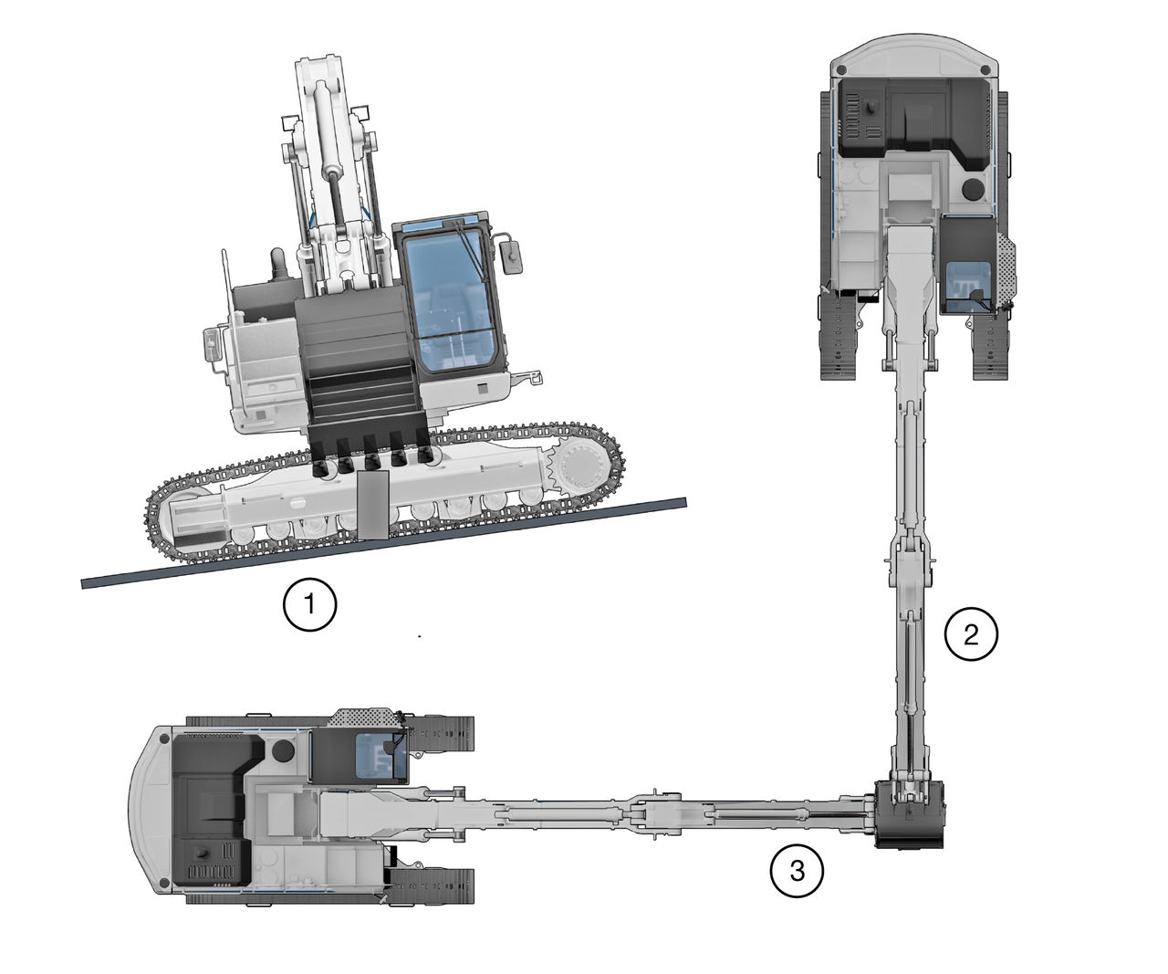
- Machine on 5% Cross Slope
- Position 1
- Position 2
If the 3D position accuracy of the system does not match the position of the hub, do the IMU calibration procedure again.Confirm hub position with systems position X Y Z Hub position Boom and bucket extended X Error Y Error Z Error Bucket extended Bucket mid-position Bucket curled Boom and stick retracted Bucket extended Bucket mid-position Bucket curled Machine on cross slope Position 1 Position 2 - Measure the hub with a GNSS rover. Use a solid surface, preferably on concrete or asphalt.
- Place the bucket on the hub in each of the positions and record the position information.ADDITIONAL INFORMATION:Note: Make sure to use the same localization/coordinate system for the rover and the machine.
- Deviations of more than 3 cm in XY and 2 cm in Z must be corrected.
Previous:
Setup verification
Next:
Specifications
myTopcon NOW! support
Take your Topcon experience to the next level with myTopcon NOW! This platform is a self-service tool for your desktop or mobile device.