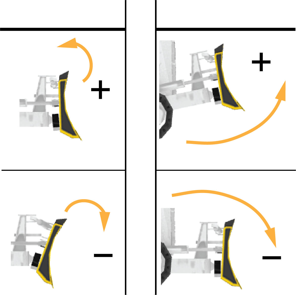
Calculations for cutting edge positions in 3D-MC follow the dozer coordinate system shown in the table below. The measurement values based on these orientations are machine-specific.
| Term | Orientation |
|---|---|
| Behind | The distance from the right blade tip to the device, measured parallel to the centerline of the dozer and towards the rear of the dozer. |
| Inside | The offset distance from the right blade tip to the device, measured towards the center of the dozer. |
| Above | The height above the cutting edge to any device is measured as the perpendicular (vertical) distance above the plane of the grousers. Always starts from the plane of the grousers, measured vertically up to the device. |
| Left/Right | Any reference within 3D-MC to left or right is always from the operator’s perspective, looking forward. |
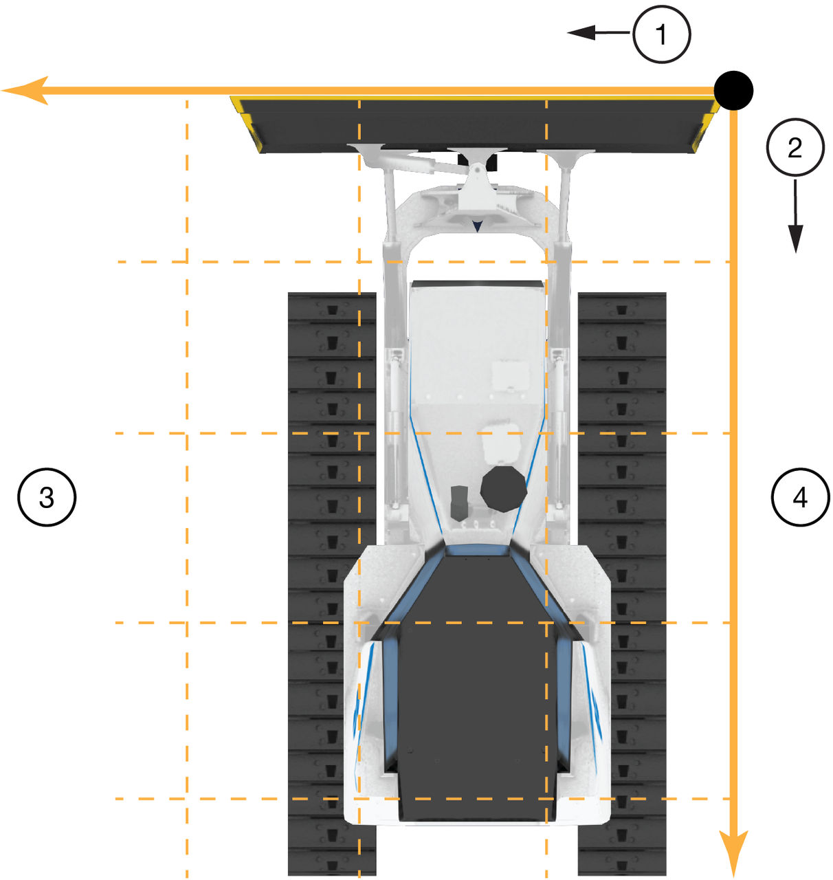
- Inside
- Behind
- Left
- Right
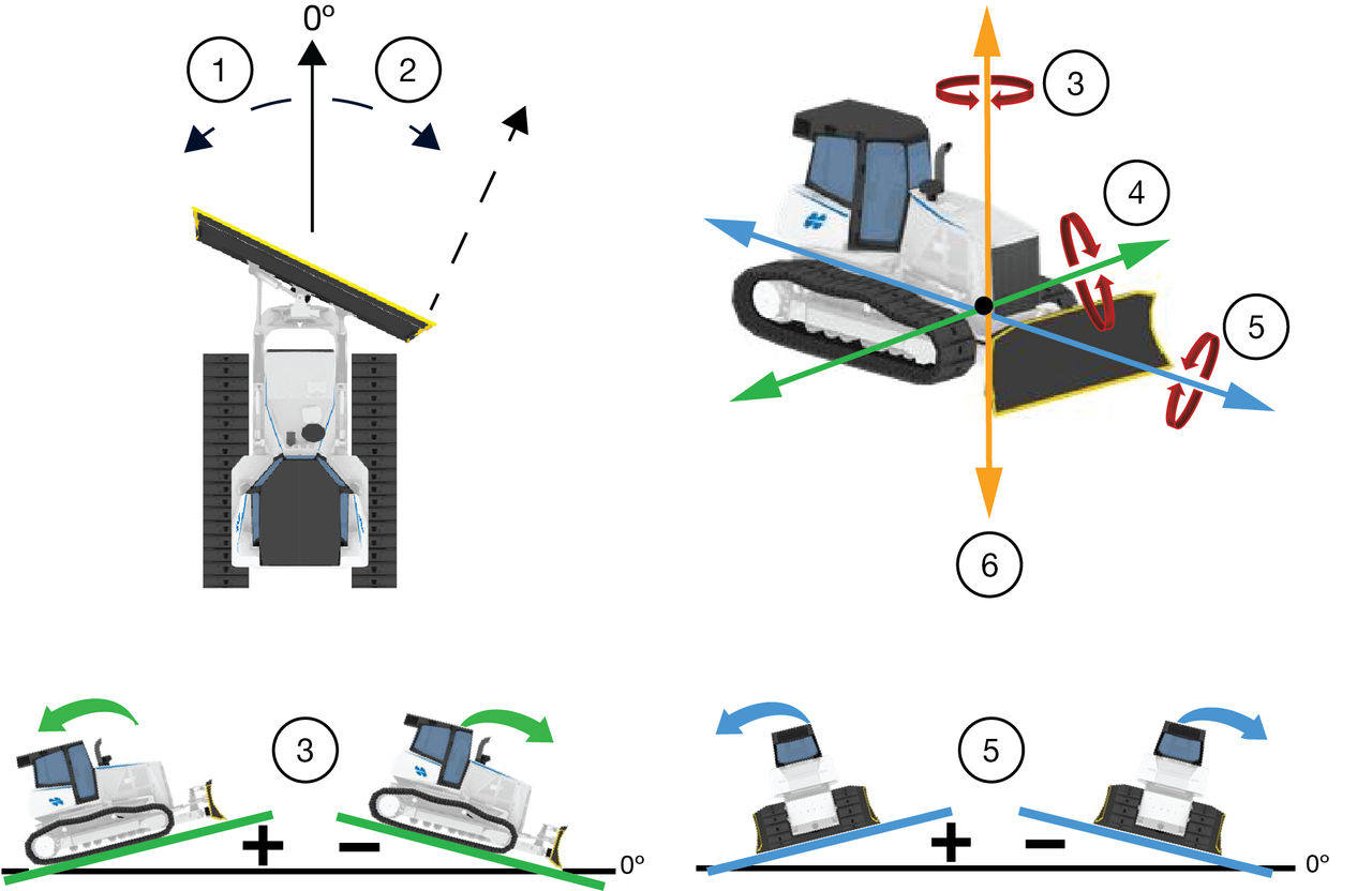
- Counter-clockwise/Left
- Clockwise /Right
- Pitch (Y-axis)
- Roll (X-axis)
- Up/Down
- Yaw (Z-axis)
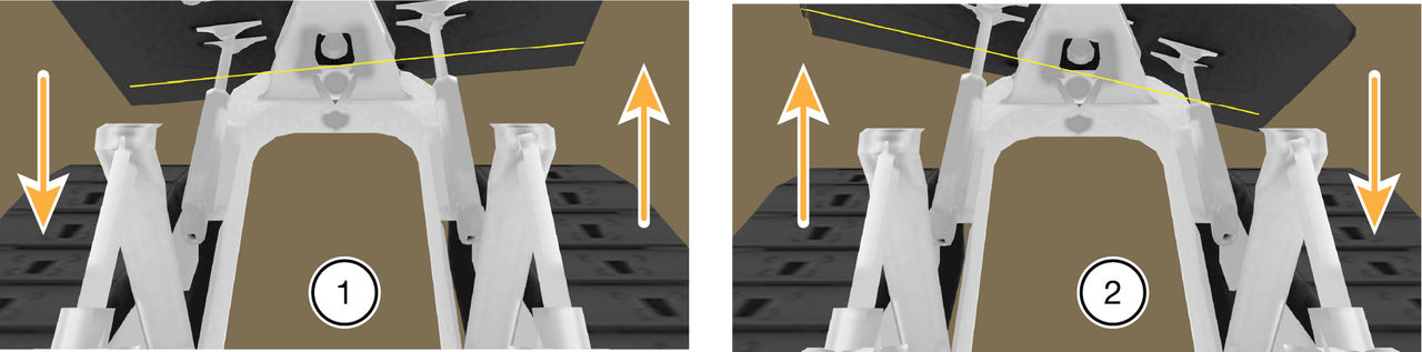
- Positive
- Negative
Previous:
Machine inspection
Next:
Bench test
myTopcon NOW! support
Take your Topcon experience to the next level with myTopcon NOW! This platform is a self-service tool for your desktop or mobile device.