- Connect dust cap to TS-i4 IMU sensor.
- Using the Ligchine-supplied hardware, mount the TS-i4 weld pad and TS-i4 to blade using the predrilled holes.ADDITIONAL INFORMATION:
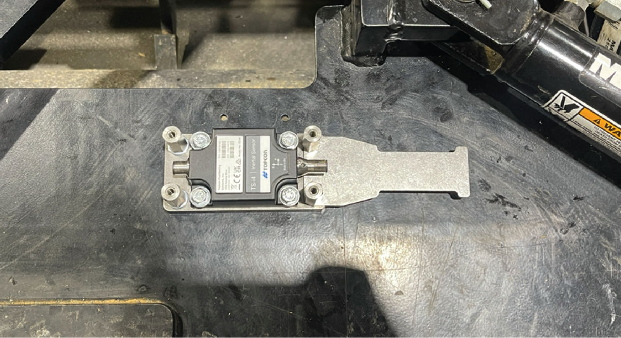
- Install the standoffs and strain relief plate to the weld pad.
- Measure and cut the necessary length of protective hydraulic hose.ADDITIONAL INFORMATION:
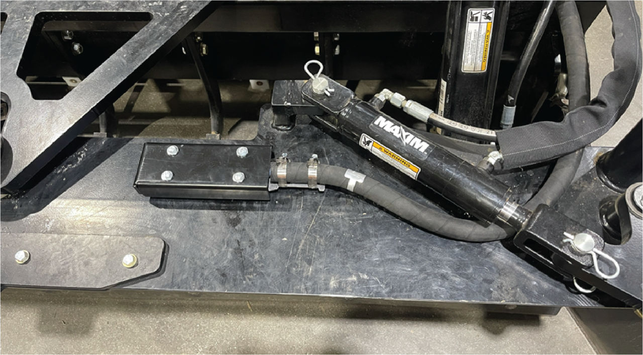
- Thread the 1-meter M12 cable through the protective hydraulic hose.
- Connect protected M12 cable to TS-i4 IMU sensor.
- Record TS-i4 IMU serial number and orientation. This information will be necessary for measurement and calibration in 3D-MC.
- Route M12 cable to CAN Open CAN Tee.
- Do not install the TS-i4 IMU sensor cover until setup and calibration are done.
- Move the blade fully with left raise/lower, right raise/lower. Add for extreme attitudes to the blade as allowable. Use service loops for strain relief. Minimum service loop size is 10 inches. Loops smaller than 10 inches can disrupt M12 CAN communication.
Previous:
System installation
Next:
Bulkhead installation
myTopcon NOW! support
Take your Topcon experience to the next level with myTopcon NOW! This platform is a self-service tool for your desktop or mobile device.