Select to configure avoidance settings to enable collision detection for points, lines, polylines, or surfaces. The avoidance area surface mode warning has five possible activation conditions.
State | Avoidance Warning Activated |
|---|---|
Above | When a part of the machine is above the avoidance area |
Below | When a part of the machine is below the avoidance area |
Above/Below | When a part of the machine is above or below the avoidance area |
Outside | When a part of the machine is outside the avoidance layer |
Off | None |
Proximity has no effect on the surface mode.
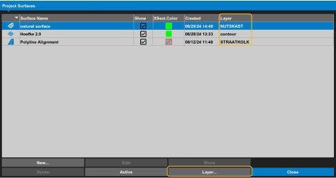
You must assign a layer to a surface to enable avoidance area warnings. Select to assign a layer to the surface.
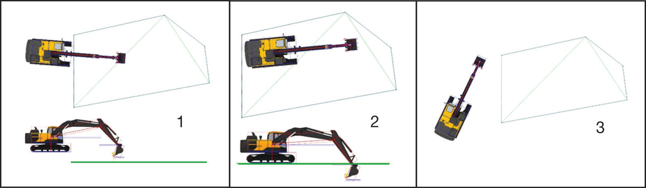
Surface Field | Off | Above | Below | Above/Below | Outside |
|---|---|---|---|---|---|
1 | No | Yes | No | Yes | Yes |
2 | No | Yes | Yes | Yes | No |
3 | No | No | No | No | Yes |
The proximity value for Above and Below makes a virtual band above and/or below the surface to cause the proximity warning.
When the surface value is set to Below, a virtual band is made between the selected surface and below the surface by the value set for the proximity parameter. If a part of the machine is between the surface and below the surface by the proximity value, the warning sounds. All parts must be above the surface or all parts must be below the surface by the proximity settings to disable the warning.
When the surface value is set to Above, a virtual band is made between the selected surface and above the surface by the value set for the proximity parameter. If a part of the machine is between the surface and above the surface by the proximity value, the warning sounds. All parts must be below the surface or all parts must be above the surface by the proximity settings to disable the warning.
When set to Above/Below, a virtual band is made above and below the surface by the proximity value parameter. If a part of the machine is between the proximity value above and the proximity value below the surface, the warning sounds.
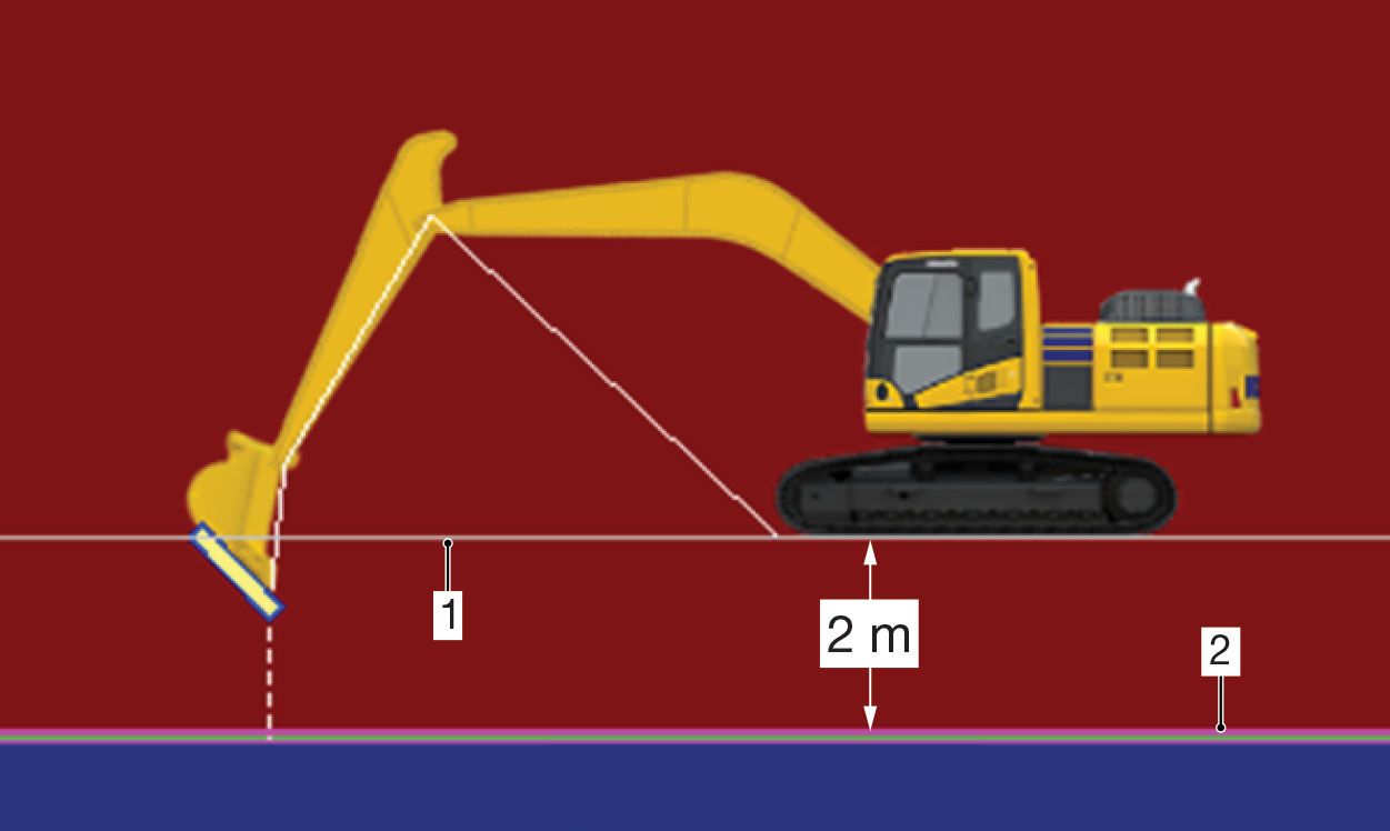
- Avoidance Above boundary
- Task surface
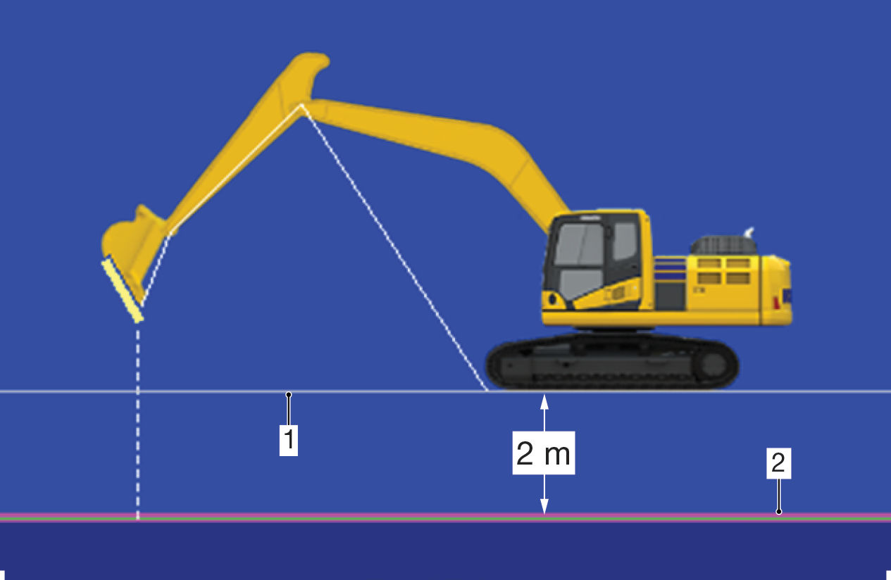
- Avoidance Above boundary
- Task surface
Only the points of the machine are compared with a virtual band. If a point of the proximity boundary (as seen in the side view) is outside this band, it does not cause the proximity warning. This occurs even though parts of the machine can cross the surface proximity band.
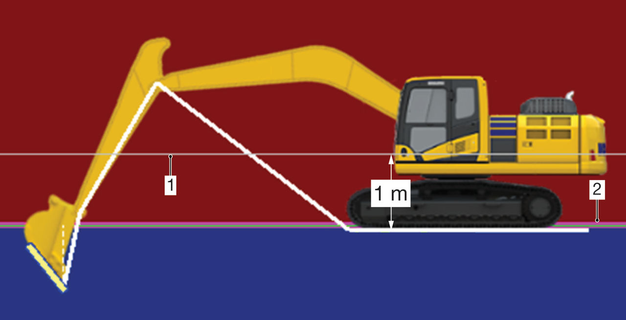
- Avoidance Above boundary
- Task surface
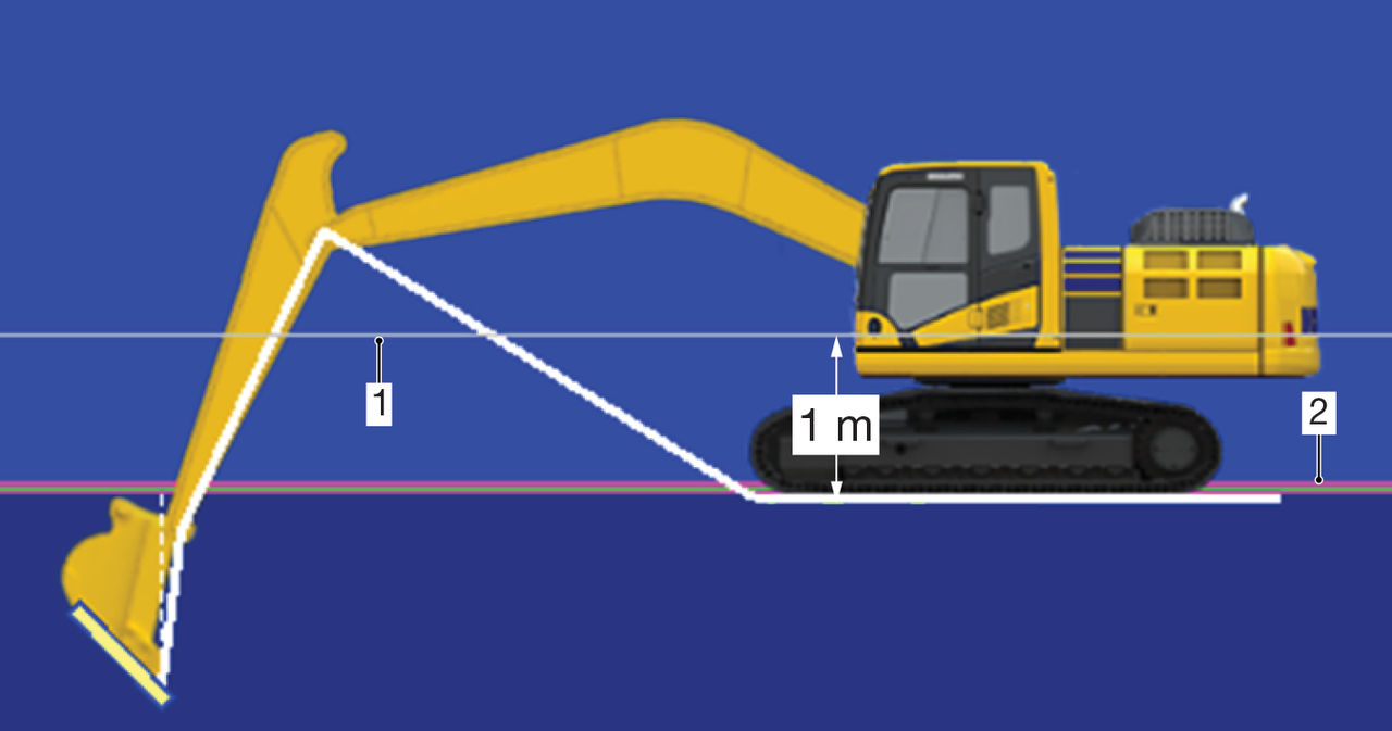
- Avoidance Above boundary
- Task surface
The bucket pivot is below the proximity and boom pivot is above the proximity, which does not cause a proximity warning. No machine points are within the boundary.
If a warning is necessary for Above or Below a full surface, set the proximity value to a large value such as 100 m.
For surfaces, the proximity is only applied to the elevation. The machine boundary around the machine does not change. The boundary does not expand as with other avoidance objects.
Previous:
Closed polylines/polygons
Next:
Guidance
myTopcon NOW! support
Take your Topcon experience to the next level with myTopcon NOW! This platform is a self-service tool for your desktop or mobile device.