Use the Working Surface Display Settings screen to change parameters, colors, and intervals on the TIN, Plane, Alignment, and Section tabs.
TIN tab
The active selection sets the working surface display options. To change the active selection, select , then select the options from Surface or Alignment.
Select . The Working Surface Display Settings screen opens with the TIN tab active by default.
- Select the checkbox(es) for the parameters that you want to show.ADDITIONAL INFORMATION:
Figure: TIN tab 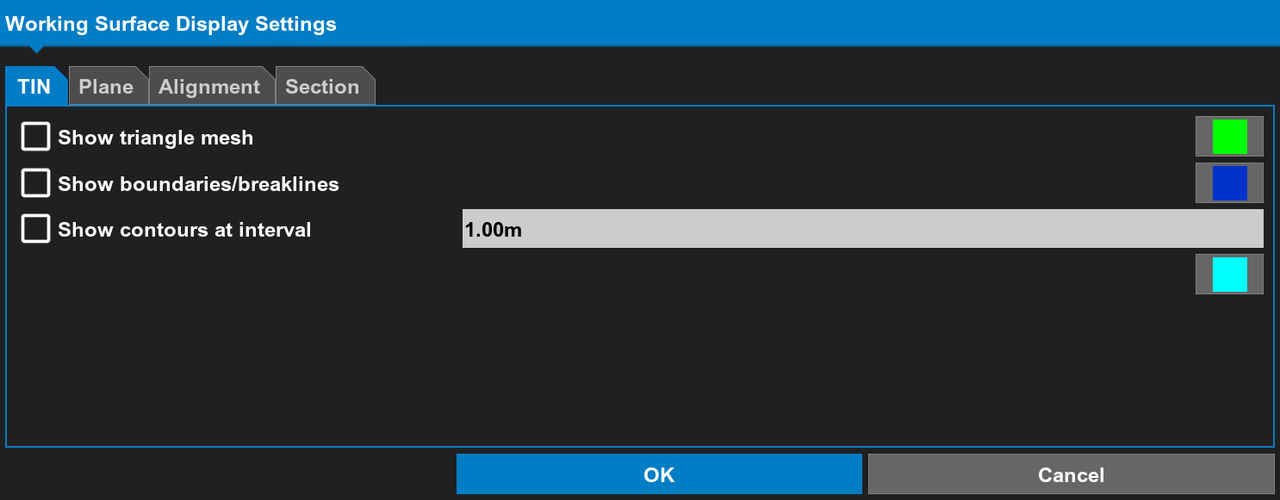
- Select the color button adjacent to the parameter(s).ADDITIONAL INFORMATION:The Color Selection screen opens.
- Select a color, then select OK.ADDITIONAL INFORMATION:
Figure: Select parameter color 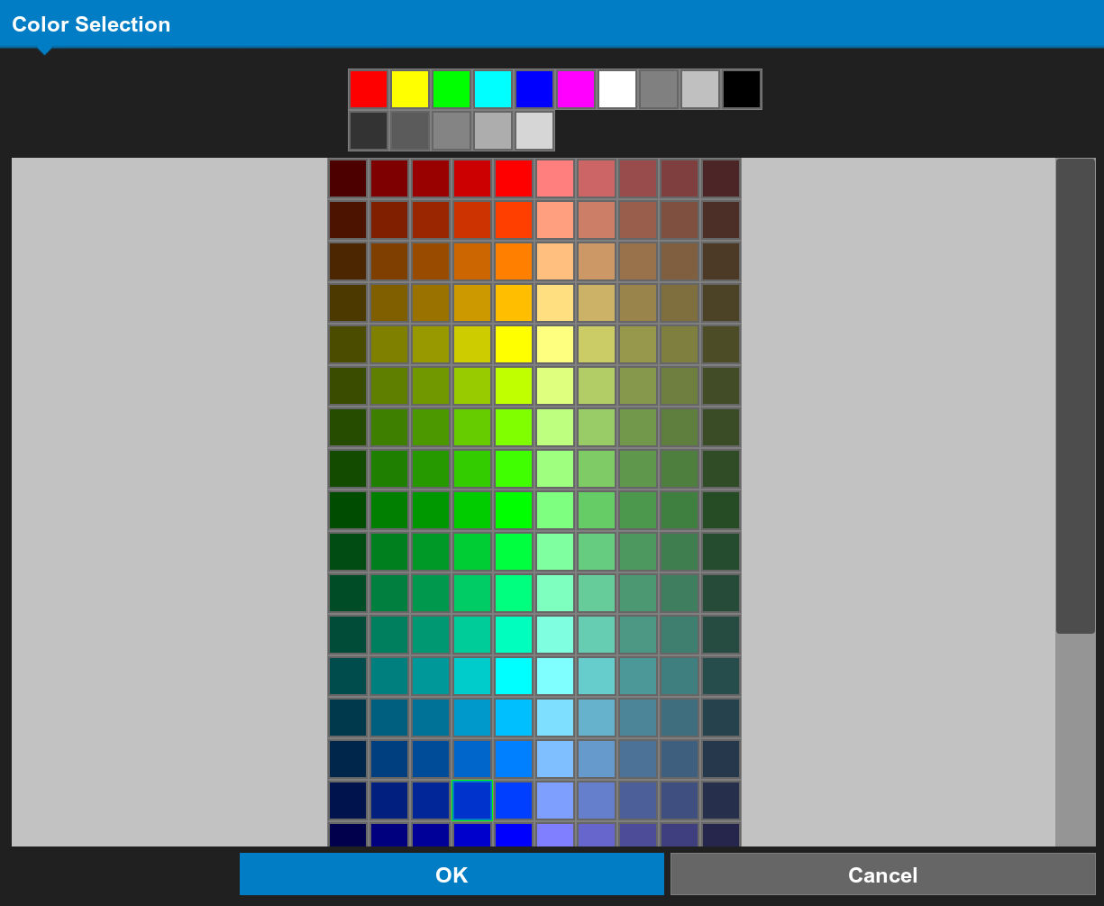
- Select the contour interval value.ADDITIONAL INFORMATION:The active surface contour line interval is the space between the contour lines on the display.
- Configure the new contour interval value, then select OK.ADDITIONAL INFORMATION:
Figure: Contour interval setting 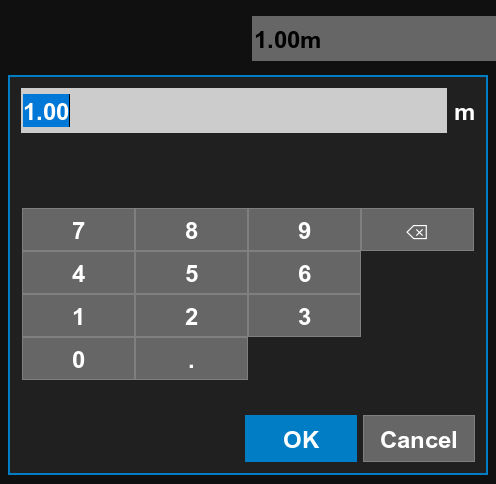
- Select OK on the Working Surface Display Settings screen to apply the changes.
Plane tab
- Select the Plane tab.
- Select Show Grid Lines to show or hide the grid lines on the main screen.ADDITIONAL INFORMATION:Grid lines are a visual interpretation of a planar surface that uses project true North and the scale factor.
Figure: Plane tab 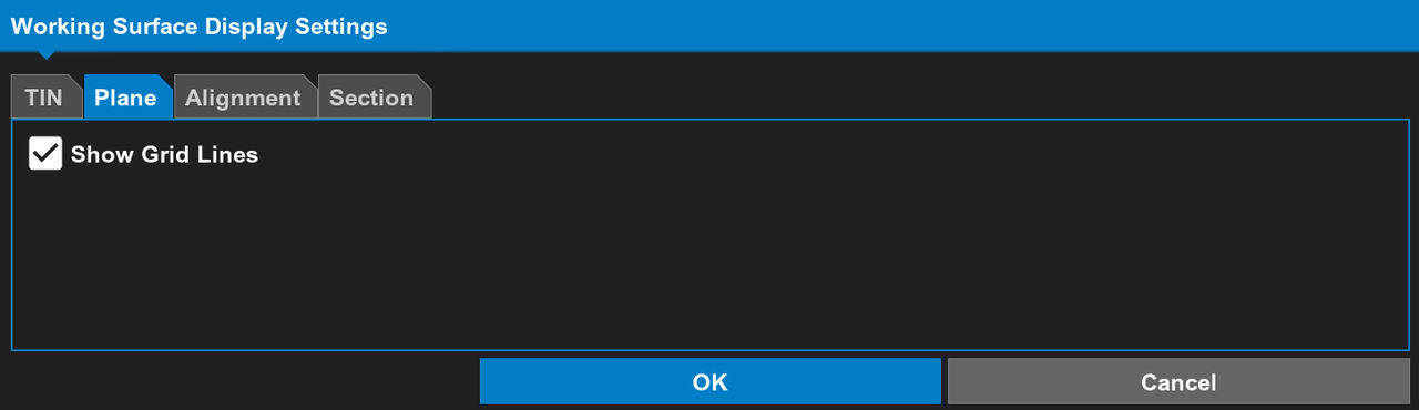
- Select OK.
- Select OK on the Working Surface Display Settings screen to apply the changes.
Alignment tab
An alignment is a line with 3D attributes that uses a profile template. An alignment can be to a road or polyline.
- Select the Alignment tab.
- Select the applicable checkbox(es).ADDITIONAL INFORMATION:Select Show alignment direction to show an arrow from the start of a station to the end of the station.Select Show regular station lines to show a horizontal line at each station derived from a 3D line with a change in elevation.Select Show station labels to show the distance intervals between alignment stations.
Figure: Alignment tab 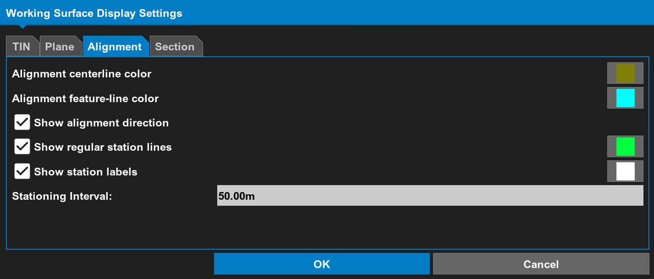 Select the Stationing interval value. Configure the new stationing interval value, then select OK. The stationing interval is the distance between station labels along the alignment.
Figure: Stationing interval setting 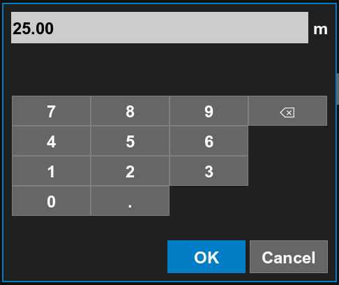
- Select the color button adjacent to the parameter(s).
- Select a color on the Color Selection screen, then select OK.ADDITIONAL INFORMATION:
Figure: Select parameter color - Select OK on the Working Surface Display Settings screen to apply the changes.
Section tab
- Select the Section tab.
- Select the applicable checkbox(es).ADDITIONAL INFORMATION:Select Show grade transitions to show grade breaks. Grade breaks are changes in surface elevation and slope. Grade transitions show as vertical lines.Select Show feature labels (alignments) to show text labels of the alignment centerline, edge of pavement, and other alignment attributes.Select Surface name in section view to show the name of the TIN surface.
Figure: Section tab 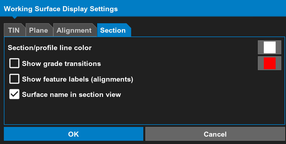
- Select the color button adjacent to the parameter(s).ADDITIONAL INFORMATION:The Color Selection screen opens.
- Select a color, then select OK.ADDITIONAL INFORMATION:
Figure: Select parameter color - Select OK on the Working Surface Display Settings screen to apply the changes.
Previous:
Display options
Next:
Point display options
myTopcon NOW! support
Take your Topcon experience to the next level with myTopcon NOW! This platform is a self-service tool for your desktop or mobile device.