The new myTopcon experience is now available. Please click here to access and start using all your apps. The legacy version will still be accessible until April 15th 2026.

GNSS and LPS system configuration

Note: If LPS-only, terminate the CAN line according to the system diagram. See the LPS System Termination topic.
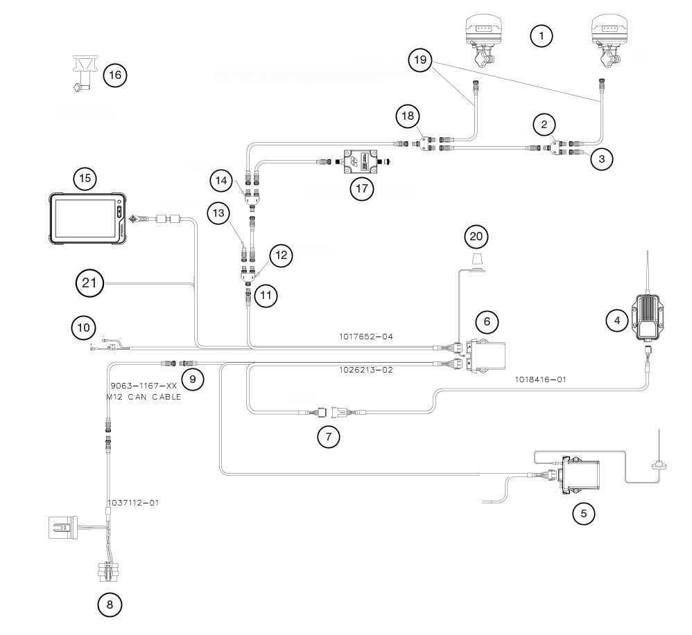
Figure: GNSS and LPS MC-X CAT grade control XTR excavator system diagram
  1. GNSS Receivers
  2. Tee
  3. Terminator
  4. Radio
  5. SL-25
  6. MC-X1
  7. Serial
  8. Machine interface connector
  9. J1939
  10. Unswitched Voltage Supply
  11. CANopen
  12. Tee
  13. Terminator
  14. Tee
  15. GX-90
  16. A7R Prism
  17. Body sensor for LPS configurations
  18. Tee
  19. One Wire Can Cables; Main Antenna Yellow; Aux Antenna Black
  20. Wi-Fi Antenna
  21. Ignition switched input

myTopcon NOW! support

Take your Topcon experience to the next level with myTopcon NOW! This platform is a self-service tool for your desktop or mobile device. 

Product manuals
paper icon
Communications
phone icon
E-learning
hat icon
Quick start guides
support icon
Firmware & software updates
cloud icon
Troubleshooting
webinars icon