- Select the Slope button on the 3D-MC main screen.ADDITIONAL INFORMATION:
Figure: Slope button 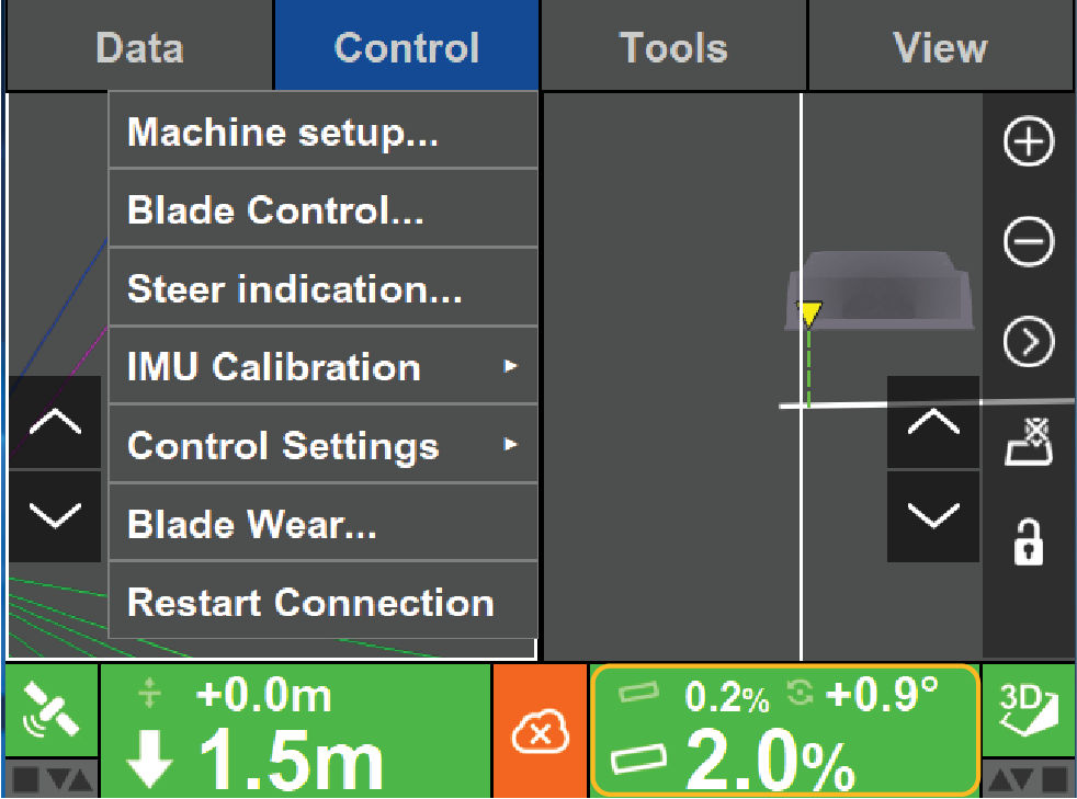 The Adjust Slope screen opens.
 - Select IMU Calibrated Values to see the list of the live values in the system.ADDITIONAL INFORMATION:
Figure: Adjust slope 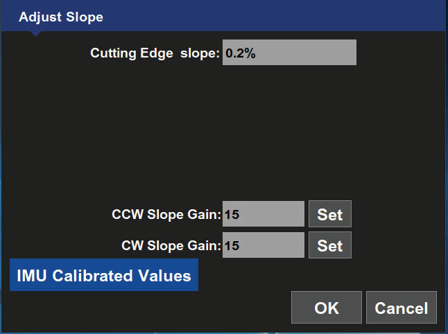
- Make sure that the blade cross slope, body cross slope, and body mainfall values match those measured with a smart level within 0.2%.
- With the blade square, slowly lift it to its maximum height.ADDITIONAL INFORMATION:While the blade moves, the blade cross slope values can vary but must be within 0.2% of the measurement made in the lowered position. If a value varies more than 0.2%, then the calibration to compensate for the orientation of the blade IMU is not accurate.
- Rotate the blade fully clockwise and record the maximum rotation angle shown on the screen.ADDITIONAL INFORMATION:When the blade is squared, the blade rotation must be 0 degrees.
- Rotate the blade fully counter-clockwise and record the maximum rotation angle.ADDITIONAL INFORMATION:Both maximum values must be approximately the same (one is a positive angle and the other is a negative angle). The absolute values of these two angles must be within less than 1 degree of each other.
- With the machine parked on the planar surface, use a smart level and magnets to transfer the cross slope of the machine to an easily accessible area on the rear of the machine.ADDITIONAL INFORMATION:
Figure: Transfer cross slope 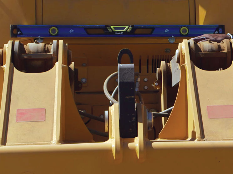
Previous:
Body heading calibration
myTopcon NOW! support
Take your Topcon experience to the next level with myTopcon NOW! This platform is a self-service tool for your desktop or mobile device.