AUTO
- Select or
 (if available) to show the Control Configuration screen with the AUTO tab active.
 - Select Elevation, Bucket, and/or Slope Control.ADDITIONAL INFORMATION:These options let you configure the system for precise movement and to make automatic performance adjustments for advanced slope creation and alignment.Note:You can select the Auto Control shortcut for access to the Elevation, Bucket, and Slope Control controls.
Figure: AUTO tab 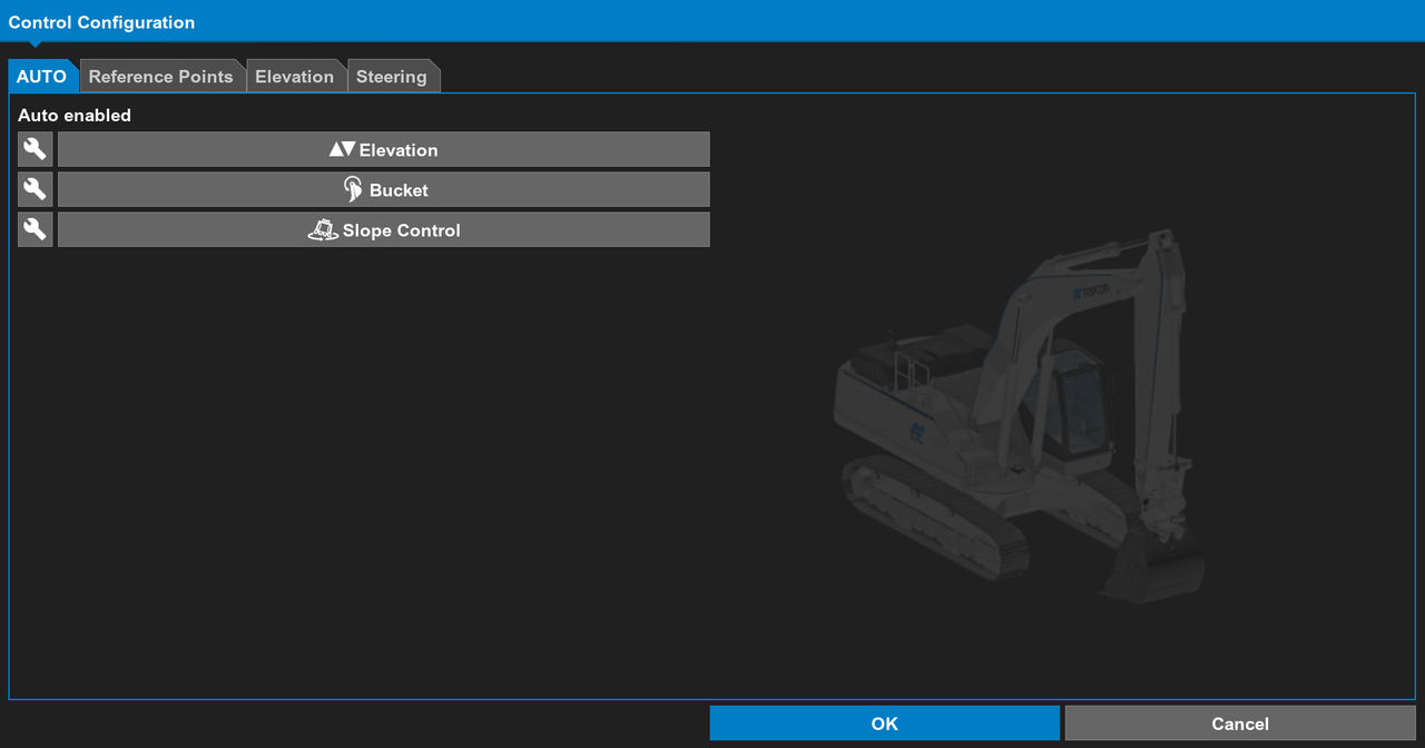
- Select the
 icon to open the Advanced Control Configuration screen on which you can make further adjustments.
Reference points
The elevation and steering POI show on the bucket image.
- Select the excavator Slope Control button to show the Control Configuration screen with the Reference Points tab activeADDITIONAL INFORMATION:The Elevation Reference Point and the Steering Reference Point show the point of interest (POI) on the bucket on the main screen. Set the Elevation Point Alignment to Vertical or Perpendicular.When locked, the Elevation POI controls both the elevation and the steering reference position.
Figure: Control configuration reference points tab 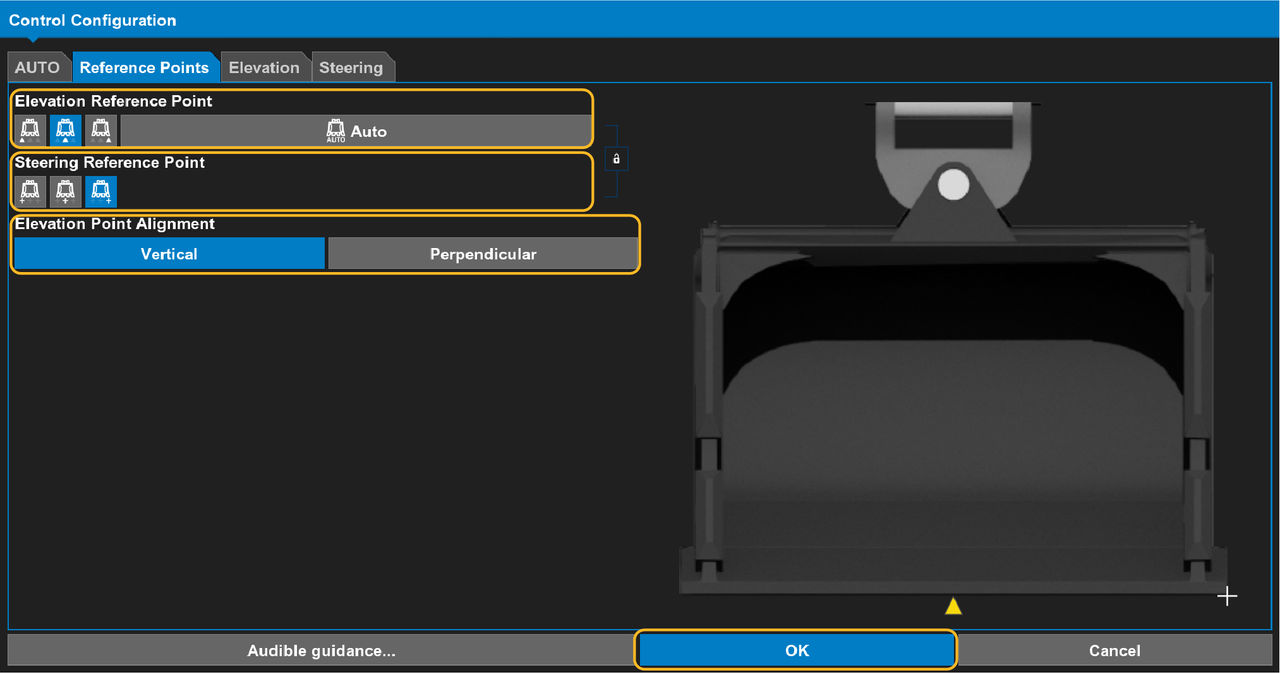
- Select Auto to set the Elevation Reference Point to the POI closest to the design.
- Select Vertical or Perpendicular to set the Elevation Point Alignment.ADDITIONAL INFORMATION:
Figure: Vertical (left) and perpendicular (right) elevation point alignment 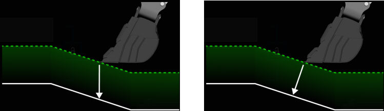
- If necessary, lock the reference points configuration.ADDITIONAL INFORMATION:
Figure: Locked unlocked 
- Select OK.
Elevation
- Select the Elevation Control button to open the Control Configuration screen with the Elevation tab active.ADDITIONAL INFORMATION:The Design Surface Offset shows the distance from the bucket to grade. For example, if the design surface offset value is 1.00 ft. (0.3 m), the grade is 1.00 ft. (0.3 m) higher than the design surface. Select Zero to set the Design Surface Offset to zero or select Match to set it to match the current elevation.
Figure: Control configuration elevation tab 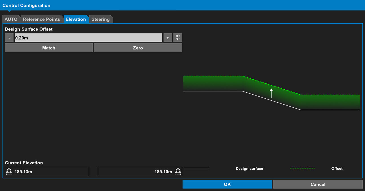
- Set the design surface offset.
- Select OK.
Steering
- Select to show the Control Configuration screen with the Steering tab active.
- Select the Alignment feature from the drop-down list.
- If it is necessary, create an Additional steer offset.ADDITIONAL INFORMATION:Additional steer offset moves the centerline left/right by the specified value.
- Use the -, +, and number controls to set the offset. Alternatively, select Match.ADDITIONAL INFORMATION:Match uses the POI of the bucket to automatically calculate the distance from the centerline and apply that value as the offset.
- Select OK.ADDITIONAL INFORMATION:
Figure: Steering 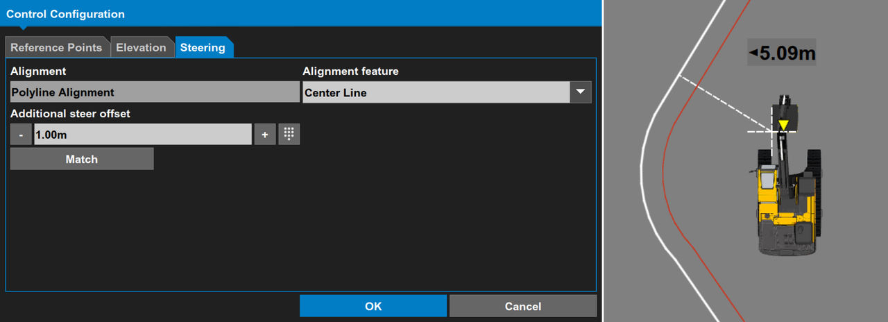
- Open the Context menu, then select Display Text to show text on the main screen.ADDITIONAL INFORMATION:
Figure: Context menu 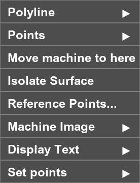
- Select the Reference point shortcut.ADDITIONAL INFORMATION:
Figure: Reference point shortcut options 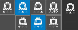
- Select the steering POI indicator.ADDITIONAL INFORMATION:
Figure: Steering POI indicators 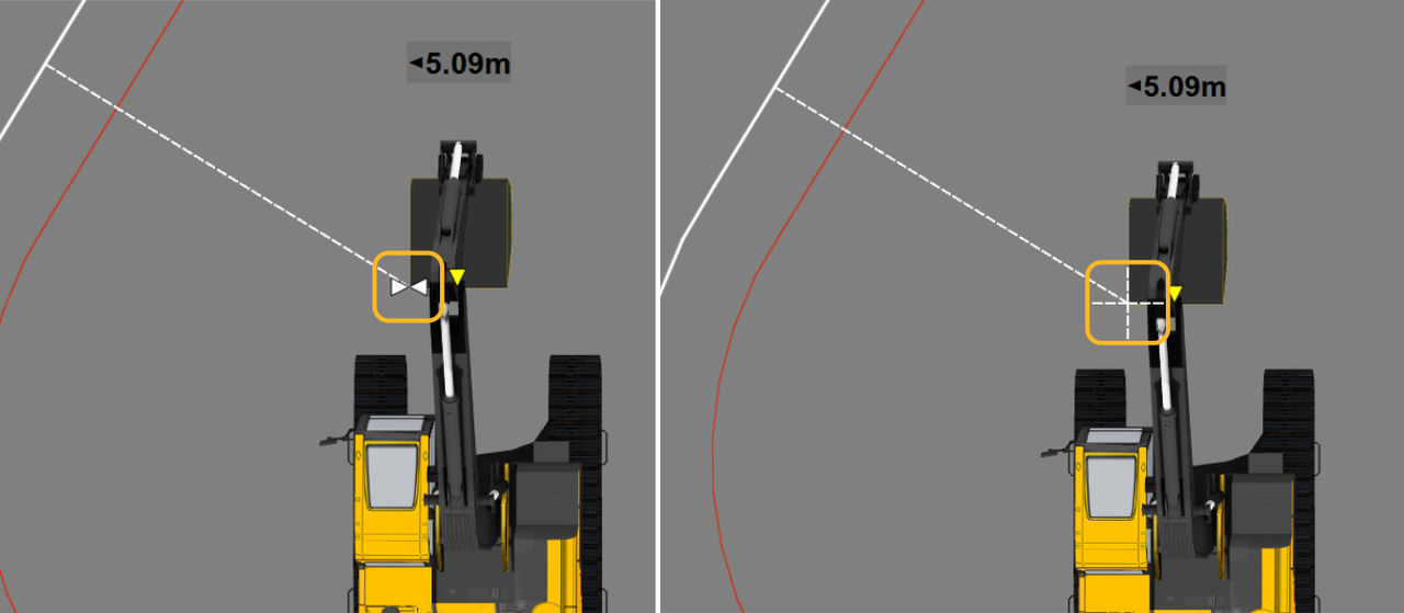
Previous:
Slope control button
myTopcon NOW! support
Take your Topcon experience to the next level with myTopcon NOW! This platform is a self-service tool for your desktop or mobile device.